
 Introduction
 Theory
 Simulation
 Self-evaluation
 Procedure
 Exercises
 References
Objectives
After completing this experiment you will be able to:
- Understand about WiMAX networks, standards, limitations
- Get familiar with adaptive modulation techniques used with WiMAX
Time Required
Around 3.00 hours
WiMAX Network
WiMAX stands for Worldwide Interoperability for Microwave Access. It is a broadband wireless point-to-multipoint specification from the IEEE 802.16 working group. It was developed by Institute of Electrical and Electronics Engineers (IEEE) in June 2001. WiMAX is designed to operate as a wireless MAN (Metropolitan Area Network). It is a telecommunications protocol that provides fixed and mobile Internet access.
Standards
• The IEEE 802.16 WiMAX standard specified for the 10 to 66 GHz ranges.[i]
• 802.16d was updated by 802.16a in 2004 to 802.16-2004. It added specification for the 2 to 11 GHz range. 802.16d, it also known as "fixed WiMAX”.
• 802.16e was updated by 802.16d in December 2005. It is known as "roaming and mobile WiMAX" and uses scalable orthogonal frequency-division multiplexing (OFDM). It has potential benefits in terms of coverage, self installation, power consumption, frequency re-use and bandwidth efficiency.
• 802.16e also adds a capability for full mobility support
• 802.16m (New) The Institute of Electrical and Electronics Engineers is expected this year in 2011 to provide final approval for the 802.16m standard, also known as "WiMAX 2" [iii] . However it plans on testing out 802.16m sometime next year in the hopes of deploying it in 2012.
Following table shows the differentiate among IEEE 802.16,802.16d and 802.16e
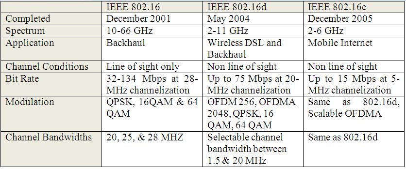 Illustration of different WiMAX standards
Comparison of Wi-Fi and WiMAX
The following table shows how WiFi is different from WiMAX
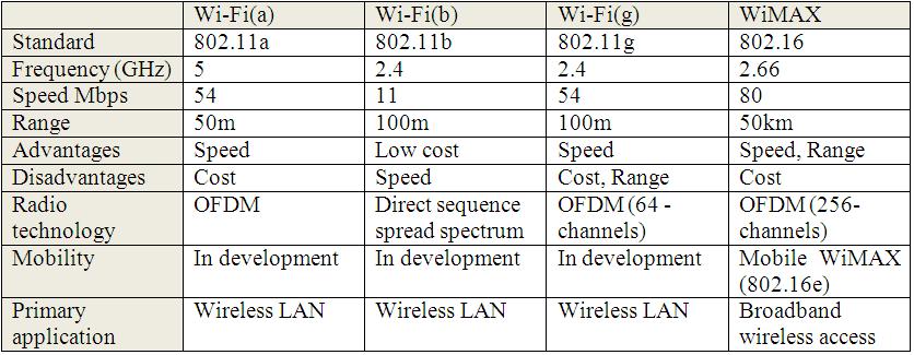 WiFi vs WiMAX [ii]
How WiMAX works ?
WiMAX is possible through broadband access to DSL lines. The working method of WiMAX is different from Wi-Fi network, because Wi-Fi system can be connected via LAN card or router, while the connectivity of WiMAX network constitutes of two parts in which one is WiMAX tower or booster also known as WiMAX base station and second is WiMAX receiver or Customer Premise Equipment (CPE).
WiMAX technology providers build a network with the help of towers that enable communication access over many miles. The broadband service of WiMAX technology is available in coverage areas. The coverage areas of WiMAX technology separated in series of over lied areas called channel.
When a user sends data from one location to another, the wireless connection is transferred from one cell to another cell. When signal transmit form user to WiMAX base station or base station to user (WiMAX receiver), the wireless channel faces many attenuation such as fraction, reflection, refraction, wall obstruction etc. These all attenuation may cause of distorted, and split toward multi path. The target of WiMAX receiver is to rebuild the transmitted data perfectly to make possible reliable data transmission.
Limitations of WiMAX
WiMax cannot provide highest performance over 50 kilometers. As the distance increases, bit error rate reduces the performance. Reducing distance to less than 1km allows a device to operate at higher bit rate. A user closer to base station gets better speed at around 30 Mbps.
As an available bandwidth is shared between no. of users, performance depends on number of active users connecting to that base station. So this needs a use of Quality of Service (QOS) mechanism to provide a minimum guaranteed throughput.
Modulation Shemes
Modulation is a technique of transfer information through a medium.[v] Modulation is used because of noise in the signal and signal attenuation. Basically in WIMAX Digital Modulation Technique are used. Digital Modulation Technique is known as conversion from digital to analog and reverse is known as demodulation.[vi]
In WIMAX following modulation techniques are used
- BPSK: Binary Phase Shift Keying.
- QPSK(1/2): Quadrature Phase Shift Keying.
- QPSK(3/4): Quadrature Phase Shift Keying.
- 16QAM(1/2): Quadrature Amplitude Modulation.
- 16QAM(3/4): Quadrature Amplitude Modulation.
- 64QAM(2/3): Quadrature Amplitude Modulation.
- 64QAM(3/4): Quadrature Amplitude Modulation.
- BPSK-It is very simple PSK(Phase Shift Keying).Its phase is separated by 180 degree.In this one bit can coded in one symbol.
- QPSK-It also a type of PSK(Phase Shift Keying).Two bits coded in one symbol.It is two dimension signalling.
- QAM-It is combination of Phase Modulation and Amplitude Modulation.It is advantageousn in performance of noise.In thin n bits can coded in one symbol.
Now one importent question why different modulation techniques are used in WIMAX?
Different modulation technique perform good task for a certain distance.Some modulation scheme does not work for a long distance.
Here some terminology,expression and table are given below
Symbol rate= Bit rate/no of bit transmitted in each symbol[vii]
which means that the symbol rates depend upon the number of bits transmitted in each symbol.
Difference between low symbol rate and high symbol rate
| i)Number of bit per symbol is more. | i)Number of bit per symbol is less. |
| ii)Power needed to transfer All bits are more. | ii)Power needed to transfer All bits are less. |
| iii)At low power, when no of bit per symbol is more then at receiver end it may not receive same bit pattern as send form sender side |
iii)At low power, when no of bit per symbol is less then at receiver end it receive same bit pattern as send form sender side |
From general concept we know that as power degrades(attenuates) with the increasing distance.
SNR=Power of Signal/Power of Noise [viii]
Here SNR depends on Power of Signal.If power of Signal is more SNR value is more.
Now we can take an example,
In BPSK the number of bit per symbol is 1 and in QPSK the number of bit per symbol is 2.
In BPSK if power is less, SNR value is also less and if power get attenuates over a long distance then also it can transmit properly as mentioned earlier.
Similarly in case of QPSK if power is less, the SNR value is also less and if power gets attenuates over a long distance then it may error in the signal as no
of bit per symbol is more than BPSK.
In the table given below shows the different scheme of modulation are given along with SNR values and maximum distance cover
| Modulation Scheme | No. of bit per symbol | SNR Value | Maximum Distance Cover(in KM.) |
| BPSK | 1 | 6.4 | 5 |
| QPSK(1/2) | 2 | 9.4 | 4.5 |
| QPSK(3/4) | 2 | 11.2 | 3.7 |
| 16QAM(2/3) | 4 | 16.4 | 3.1 |
| 16QAM(3/4) | 4 | 18.2 | 2.5 |
WIMAX module for NS-2
Module name:ns2-wimax-awg
Module Details:Initially this module was developed at National Institute of
Standards and Technology but later on it was decided to combine individuals
team effort supported by Application Architecture Task Group(AATG), Wimax Forum
and National Institute of Standards and Technology. By applying this patch we
can directly use WiMAX in the existing NS-2. All the features available are
listed in NS-2_Release_2_6_Documentation.pdf document
[ix], including
- OFDMA for physical layer
- Time Division Duplexing (TDD)
- Schedulers for link allocation to registered Mobile Stations (MSs) according to bandwidth requested
- IEEE 802.16e MAC layer extensions
- Fragmentation and reassembly of frames
- Fast fading models: ITU PED A, PED B and VEHIC A
- QoS scheduling, ARQ
How to download and install patch for WIMAX?
step-1: Go to url http://code.google.com/p/ns2-wimax-awg/
step-2: Click on Downloads.
step-3: Click on ns2-Release-2.6.tar.gz for getting patch and click on NS-2_Release_2_6_Documentation.pdf for documentation.
step-4: Click on ns2-Release-2.6.tar.gz here we will get patch file, sample script and some document.
step-5: Extract ns2-Release-2.6.tar.gz
step-6: Copy ns-2.31-WiMAX_AATG_R2.6.patch and paste in to ns-2.34
step-7: Apply patch
Now ns-2.34 is ready with WIMAX.
Addressing Format in ns2
The Default address format
The address space consists of two part node id and port id.Here node id is flat, we can say if there is n number of node then its id will be 1 to 10.
The Hierarchical address format
In hierarchical addressing node-id has three level as x.y.z, where x is domain number, y is cluster number and z is number of node in each cluster.
Example
$ns node-config -addressType hierarchical (Here,Hierarchical addressing is used)
AddrParams set domain_num_ 2 (In this line it is mentioned tha there are two domain exist)
lappend cluster_num 1 1 (This line indicates each domain contains 1 cluster)
AddrParams set cluster_num_ $cluster_num
lappend eilastlevel 1 2 (In this line it is mentioned that there is 1 node in 1st cluster and 2 node in second cluster)
AddrParams set nodes_num_ $eilastlevel
Wireless (New) Trace File Format
The following describes the various fields of asimulation trace file for wireless networks in the
Node Id |
||||||||||||||||||||||||||||||||||||||||||
Description of New Trace File Format
| Field No | Field Name | ||
| 1 | Event | Any event in network wrt a packet |
s: send |
| 2,3 | Timestamp | When the event occur | -t < time > |
| 4,5 | Adjacent Node Info | Contain info about next node | -Hs < Current Node id > |
| 6,7 | -Hd < Next Hop id toward target node > | ||
| 8,9 | Node Property | Property of Node | -Ni < Node id > |
| 10,11 | -Nx < x cordinate > | ||
| 12,13 | -Ny < y cordinate > | ||
| 14,15 | -Nz < z cordinate > | ||
| 16,17 | -Ne < Node energy level > | ||
| 18,19 | -Nl < Trace Level like > | ||
| 20,21 | -Nw < Reason for event > | ||
| 22,23 | Ptk Info MAC | information of Packet at MAC level | -Ma < ??? > |
| 24,25 | -Md < MAC address of destination > | ||
| 26,27 | -Ms < MAC Address of Source > | ||
| 28,29 | -Mt < Type of MAC > | ||
| 30,31 | Pkt Info IP | Information of Packet at IP level | -Is < Sourse Address,Source Port > |
| 32,33 | -Id < Destination Address,Destination Port > | ||
| 34,35 | -It < Packet Type > | ||
| 36,37 | -Il < Packet Length > | ||
| 38,39 | -If < Flow Id > | ||
| 40,41 | -Ii < Unique Id > | ||
| 42,43 | -Iv < TTL Value > | ||
| Others | Pkt Info | Information of Packet at Application level.Some Specific Fields are: TCP: Tranmission Control protocol AODV: Ad hoc On-Demand Distance Vector Routing DSR: Dynamic Source Routing. ARP: Address Resolusion Protocol. CBR: Constant Bit Rate. |
e.g, ARP: -Po < ARP Request or Reply > -Pm < source MAC address > -Ps < source address > -Pa < destination MAC address > -Pd < destination address > |
|
CBR: -Pi < sequence number > -Pf < no. of times this packet was forwarded > -Po < optimal no. of forwards > |
|||
|
TCP: -Ps < sequence number > -Pa < acknowledgement number > -Pf < no. of times this packet was forwarded > -Po < optimal no. of forwards > |
|||
|
DSR: -Pn < no. Of nodes traversed > -Pq < routing request flag > -Pi < route request sequence no. > -Pp < routing reply flag > -Pl < length of reply > -Pe < source of source routing->destination of the source routing> -Pw < error report flag ? > -Pm < no. of errors > -Pc < report to whom > -Pb < error in (from link X->link Y) > |
Wireless Trace File Format
[xi] & [xii] Sample Example of new Trace File Format:s -t 3.000000000 -Hs 0 -Hd -2 -Ni 0 -Nx 451.50 -Ny 393.62 -Nz 0.00 -Ne -1.000000 -Nl AGT -Nw --- -Ma 0 -Md 0 -Ms 0 -Mt 0 -Is 0.0 -Id 2 .0 -It tcp -Il 40 -If 2 -Ii 0 -Iv 32 -Pn tcp -Ps 0 -Pa 0 -Pf 0 -Po 1Explanation:
s: this field is for event,meaning of this packet send and can varry s: send,f: forward: dropped,r: recieved

-t 3.000000000:  '-t' is a tag for time and timestamp value is 3.000000000

-Hs 0 -Hd -2: This field contains the information of next node
-Hs 0 is current node id is 0
-Hd -2  is next hop id is 2

-Ni 0: Node id = 0
-Nx  451.50: x coordinate of node 451.50
-Ny  393.62: y coordinate of node 393.62
-Nz  0.00: Z coordinate of node 0.00
-Ne  -1.000000: Energy Level of the node is 1.000000
-Nl  AGT: Trace Level is AGT
-Nw _ _ _ : This is reason for the event which is disable

-Md 0: MAC address of the destination is 0
-Ms 0: MAC address of source is 0
-Mt 0: MAC type is 0

-Is 0.0: Source address is 0 & Source poet is 0
-Id 2.0: Destination address is 2 & Destination port is 0
-It tcp: Packet Type is TCP
-Il 40: Length of the packet is 40byte
-If 2: Flow id is 2
-Ii 0: unique id is 0
-Iv 32: TTL is 32
After these fields remaining are variable field depending upon the protocol, as mentioned in table
-Pn tcp: Here TCP protocol is working
-Ps 0: Sequence Number is 0
-Pa 0: Acknowledgement is 0
-Pf 0: No of times packet is forwarded is 0
-Po 1: Optimal no of packet forwarded is 1

