
 Introduction
 Theory
 Simulation
 Self-evaluation
 Procedure
 Exercises
 References
Objectives
After completing this experiment you will be able to:
- Understand about the basics of Zigbee Networks
- Learn the simulation of star topology in ns2
Time Required
Around 3.00 hours
ZigBee Network
The name ZigBee originates from the zig-zag waggle dance of Honey bees [i]. ZigBee is based on IEEE 802.15.4 standard for Low Rate Wireless Personal Area Network (LR-WPAN). ZigBee uses radio frequency (RF) for communication and operated on one of the three different radio bands: 868 MHz in Europe, 915 MHz in the USA and Australia, and 2.4 GHz in world wide.
| It was created by the Institute of Electrical and Electronics Engineers (IEEE),for low rate personal area network. | It was created by the ZigBee Alliance. |
| IEEE 802.15.4 focuses on lower two layers(physical and data link layer) of OSI. | ZigBee Alliance aims to provide the upper layers (from network to the application layer) of OSI based on IEEE 802.15.4. |
| Its main purpose is the communication between two devices. | Its main purpose is to create a network topology and add features such as security, encryption, association and in the upper layer application services. |
| ZigBee is a low-cost, low-power, wireless mesh network. | Bluetooth was designed for low power consumption with short range communications. |
| The operational range of ZigBee is 10-75m. | The operational range of Bluetooth is 10m. |
| It allows up to 254 nodes. | It allows up to 8 slave nodes in a basic master-slave piconet set-up. |
| Battery life is 100-1000 days. | Battery life is 1-7 days. |
Features & Characteristic of ZigBee Technology
The features and characteristics of Zigbee technology [v] are as follows:
- ZigBee network connect several units and control through one button.
- ZigBee network is controlled by a remote control device at a specific range and as the control device is present centrally,it reduces manpower.
- ZigBee devices are reliable because they are designed on low-power frequency.
- ZigBee technology supports 3 different types of devices.They are coordinator, router and end-user devices.
- Coordinators are the primary devices to help in activation of the system by collecting the data in form of memory.
- Routers are the secondary devices that function by sending information to the destination.
- End-user devices are basically receivers that are not able to send information itself.
Application of ZigBee Technology
- ZigBee technology is programmed in a chip form and that chip is used in many devices to function automatically. For example controlling and monitoring a whole factory unit while sitting in one cabin is possible by using ZigBee technology.
- Building automation
- Consumer electronics
- Automatic meter reading
- Home automation
- Managing health care system
- Retail management
- Telecommunications
ZigBee Technology used in many applications [v]. Some of them are described below:
Component of IEEE 802.15.4 LR-WPAN
Different component of IEEE 802.15.4 LR-WPAN [vi] are:
- Coordinator : Coordinator controls and monitor the established network. Based on their operation scope two different kinds of coordinators are present.The PAN-Coordinator, which acts as a coordinator for the entire PAN and the ordinary coordinator,which function within the scope of a cluster.
- Cluster : A cluster is a small section of a bigger network, which has its own coordinator. Groups of clusters communicate with a central PAN-Coordinator to form the PAN in a mesh topology.
- Device/End Node : A device is either a reduced/full function device, these are the end devices(leaf of a tree structure). Any device that is not a co-ordinator is an end node (device).
- Personal Operating Space(POS) : It is the operating range of a node in all directions, and is a constant irrespective of being in motion or stationary.
There are 14 PHY and 35 MAC Primitives defined by the IEEE 802.15.4 standard [iv]. The LR-WPAN supports two types of devices called the Full Function Device and the Reduced Function Device.
- Full Function Device(FFD) : It is a device which supports all the 49 primitives supported by the technology [iv]. It acts as a PAN coordinator, a Coordinator, or just as an end node (device). Also an FFD can function as a routing device in certain network topologies where data transfer among FFD is allowed (EX: peer-to-peer communication).
- Reduced Function Device(RFD) : It is a device with reduced functionality which can only function as an end device or node. It can only communicate with the coordinator. Their functionality is extremely low. So these devices are intended for simple applications like a light switch, etc. They merely send information to the coordinator at regular intervals about the status of the device it is monitoring. It can only support a maximum of 38 primitives [iv].
Network Topologies
A Low rate WPAN supports three different types of topologies [vi].
- Star Topology
- Peer-to-Peer Topology
- Cluster Tree/Mesh Topology
Star Topology
In the star topology, the PAN coordinator have the primary control. In this topology devices monitore their application and report it to the coordinator.The Figure-01 shows star topology.
 Figure-01: Star topology
 Peer-to-Peer Topology
The peer-to peer topology has a PAN coordinator and any device can communicate with any other device.This topology allows more complex network formations.Figure-02 shows peer-to-peer topology.
 Figure-02: Peer-to-peer topology
In the above figure the possible communication scenarios are between node-to-node, node-to-coordinator, coordinator-to-node. As is evident if two devices need to transfer data, both have to be full function devices. A peer-to-peer network can be ad-hoc, self-organizing and self-healing.
Cluster-Tree Topology
In cluster tree topology several small clusters are present and are able to communicate peer-to-peer and can be controlled with a PAN coordinator. Each cluster can have its own coordinator and the coordinators can communicate with the PAN Coordinator. We can choose a PAN coordinator among several existing clusters.Figure-03 shows cluster-tree topology.
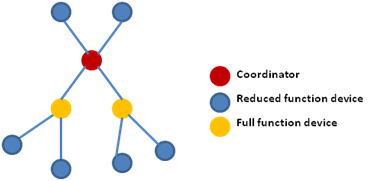 Figure-03: Cluster-tree topology
 ZigBee Architecture
IEEE 802.15.4 consists of PHY and the MAC layers [vi]. The upper layers are left for application developers.
The PHY layer is responsible for activation and deactivation of the radio transceiver, ED, LQI, channel selection, clear channel assessment (CCA), and transmitting as well as receiving packets across the physical medium. Similarly, the MAC layer is responsible for beacon management, channel access, guaranteed time slots (GTS) management, frame validation, acknowledged frame delivery, association, and disassociation.
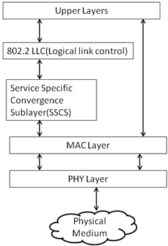 Figure-04: IEEE 802.15.4 Architecture [vi].
 The Superframe structure
The superframe structure [vi] is determined by the coordinator. IEEE 802.15.4 networks are able to operate in two different modes of operation
- Beacon mode or
- Non beacon mode
In beacon mode, the coordinator sends out periodic packets or beacons. The purpose of this is to enable all nodes to sleep between beacons and wake up when the beacon timer expires, ready to receive the beacon from the coordinator. The superframe structure is only applicable in beacon mode networks. In non beacon networks the superframe structure is disabled and nodes contend for channel access by CSMA/CA.
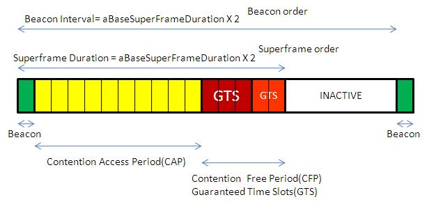 Figure-05: The superframe structure [viii]
Contention Access Period: It is the time duration in symbols during which the devices can compete with each other to access the channel using CSMA-CA and transmit the data.
Contention Free Period/Guaranteed Time Slots: Certain low-latency application devices are given exclusive rights over the channel to start transmission directly. There can as many as 7 slots assigned for GTS transmissions. These transmissions start immediately after the contention access period.
Inactive Period: It is the time period during which the coordinator would not interact with the PAN. Therefore, there will be no beacon transmissions. So the devices go to sleep mode in this duration.
Superframe Duration: The total time duration of the CAP, CFP (GTS) and a Beacon. The superframe duration doesn’t include the inactive period.
Beacon Interval: It is the time duration between two successive beacons.
The beacon and superframe orders can range from 1 to 15 inclusive but the superframe order must be less than or equal to the beacon order. When the beacon and superframe order are equal there is no inactive period between beacons, when the superframe order is less than the beacon order there is an inactive period and setting them both to 15 disables beacon mode.
Nodes Configuration
The node configurations [ix] of ZigBee network are defined below:
- The PAN coordinator in ZigBee network are defined by:
$ node SSCS StartPANCoord <txBeacon> <beacon Order(BO)> <superframeorder(SO)> ; # PAN coordinator default values txBeacon=1,BO=3,SO=3
The above syntax is use to initiate a Pan-Coordinator in a network & any device can be made pan-coordinator by using above syntax, even if any of the above parameters are omitted, then the default values in an above equation can be used.
Example:
$node_(0) sscs startPANCoord     		; # PAN coordinator default BO=3, SO=3
$node_(0) sscs startPANCoord 1 6 2	        ; # PAN coordinator with BO=6, SO=2
$ node SSCS startdevice <isFFD> <assopermit> <txBeacon> <BO> <SO> ; # Default value isFFD=1,assopermit=1,txBeacon=0, BO=3, SO=3
The above command turned on the node as a device or a coordinator, if some of the parameter is neglected than the rest of parameters will get set by default variable as defined above.
Example:
$node_ (0) sscs startDevice 0         ; # device
$node_ (0) sscs startDevice        ; # coordinator non-beacon
$node_ (0) sscs StartDevice 1 1 1  ; # coordinator beacon enabled
Energy Model
At the beginning of the simulation the node has an initial energy. This is known as initialEnergy [vii]. Energy is consumed when a node receives or transmits a packet. This energy are called rxPower and txPower.
The basic energy model is defined by class EnergyModel as shown below:
class EnergyModel : public TclObject {
public:
  EnergyModel(double energy) { energy_ = energy; }
  inline double energy() { return energy_; }
  inline void setenergy(double e) {energy_ = e;}
  virtual void DecrTxEnergy(double txtime, double P_tx) {
    energy_ -= (P_tx * txtime);
  }
  virtual void DecrRcvEnergy(double rcvtime, double P_rcv) {
    energy_ -= (P_rcv * rcvtime);
  }
protected:
  double energy_;
};
The class variable energy_ represents the level of energy in the node at any given time. The constructor EnergyModel(energy) requires the initial-energy to be passed along as a parameter. The other class methods are used to decrease the energy level of the node for every packet transmitted ( DecrTxEnergy(txtime, P_tx)) and every packet received ( DecrRcvEnergy (rcvtime, P_rcv)) by the node. P_tx and P_rcv are the transmitting and receiving power (respectively) required by the node’s interface or PHY. At the beginning of simulation, energy_ is set to initialEnergy_ which is then decremented for every transmission and reception of packets at the node. When the energy level at the node goes down to zero, no more packets can be received or transmitted by the node.
The mobile node energy trace begins “N”. The format of the trace file is given below:
N -t <time> -n <node id> -e <node energy>

