
 Introduction
 Theory
 Simulation
 Self-evaluation
 Procedure
 Exercises
 References
Objectives
After completing this experiment you will be able to:
- Learn the basic concepts about open source network simulator NS-2, and how to download, install and work with NS-2
- Defining the different agents and their applications like TCP, FTP over TCP, UDP, CBR over UDP
- Identifying and solving typical errors encountered during installation of NS-2
Time Required
Around 3.00 hours
Introduction
Network Simulator version 2 (NS-2) is discrete event packet level simulator. The network simulator covers a very large number of application of different kind of protocols of different network types consisting of different network elements and traffic models. NS-2 is a package of tools that simulates behavior of networks such as creating network topologies, log events that happen under any load, analyze the events and understand the network. The aim of this first experiment is to learn how to use NS-2, to get acquainted with the simulated objects and understand the operations of network simulation. We will also look at how to analyze the outcome of a simulation.
Platform required to run network simulator
- Unix and Unix like systems
- Linux
- Free BSD
- SunOS/Solaris
- Windows 95/98/NT/2000/XP (requires Cygwin)
Backend Environment of Network Simulator
Network Simulator is based on two languages: C++ and OTcl. OTcl is the object oriented version of Tool Command Language. While the core of NS-2 is written in C++, one uses OTcl to write simulation scripts. C++ helps in the following way:
- It helps to increase the efficiency of simulation.
- Its is used to provide details of the protocols and their operation.
- It is used to reduce packet and event processing time.
OTcl helps in the following way:
- With the help of OTcl we can describe different network topologies
- It helps us to specify the protocols and their applications
- It allows fast development
- Tcl is compatible with many platforms and it is flexible for integration
- Tcl is very easy to use and it is available in free
And of course, there is a linkage between C++ and OTcl, which allows us to run the simulation scripts.
Basics of Tcl Programming for NS-2
Network simulation with NS-2 would involve the following general steps:
- Initialization and termination aspects of network simulator object
- Defining the network topology: nodes, links, queues, mobility of nodes, if any
- Defining the network traffic: creating agents and their applications
- Setting trace for Network Animator (NAM) [optional]
- Tracing
In this section, we provide a brief overview of the most commonly used features of NS-2. This summary has been prepared based on various tutorials on, and the manual for, NS-2. See the References section for some of the different tutorials available.
Initialization
To create a new simulator we write
set ns [new Simulator]
From the above command we get that a variable ns is being initialized by using the set command. Here the code [new Simulator] is a instantiation of the class Simulator which uses the reserved word new. So we can call all the methods present inside the class simulator by using the variable 'ns'.
Creating the output files
# Create the trace files
 set tracefile [open out.tr w]
 $ns trace-all $tracefile

# Create the nam files
 set namfile [open out.nam w]
 $ns namtrace-all $namfile
In the above we create a output trace file 'out.tr' and a NAM visualization file 'out.nam'. But in the Tcl script they are not called by their names declared, while they are called by the pointers initialized for them such as 'tracefile' and 'namfile' respectively.The line which starts with # are commented. The next line opens the file 'out.tr' which is used for writing is declared 'w'. The next line uses a simulator method trace-all by which we will trace all the events in a particular format.
The termination program is done by using a 'finish' procedure
# Defining the 'finish' procedure'

proc finish {} {
     global ns tracefile namfile
     $ns flush-trace
     close $tracefile
     close $namfile
     exit 0
}
In the above, the keyword proc is used to declare a procedure called 'finish'. The keyword global is used to tell what variables are being used outside the procedure.
flush-trace is a simulator method that dumps the traces on the respective files. The command close is used to close the trace files and the command exec is used to execute the NAM visualization. The command exit closes the application and returns zero as default for clean exit.
In ns we end the program by calling the 'finish' procedure
# End the program
$ns at 125.0 "finish"
Thus the entire operation ends at 125 seconds.To begin the simulation we will use the command
# Start the the simulation process
$ns run
Defining nodes, links, queues (topology)
Way to create a node:
set n0 [$ns node]
In the above we created a node that is pointed by a variable n0. While referring the node in the script we use $n0. Similarly we create another node n2. Now we will set a link between the two nodes.
$ns duplex-link $n0 $n2 10Mb 10ms DropTail
So we are creating a bi-directional link between nodes n0 and n2 with a capacity of 10 Mb/sec and a propagation delay of 10 ms.
In NS an output queue of a node is implemented as a part of a link whose input is that node to handle the overflow at the queue. If the buffer capacity of the output queue is exceeded then the last packet arrived is dropped and here we will use a 'DropTail' option. There are other queue types such as RED (Random Early Discard) mechanism, FQ (Fair Queuing), DRR (Deficit Round Robin), SFQ (Stochastic Fair Queuing) also available.
Now we will define the buffer capacity of the queue related to the above link
# Set queue size of the link
$ns queue-limit $n0 $n2 20
So, if we summarize the above three things we get
# Create nodes

set n0 [$ns node]
set n1 [$ns node]
set n2 [$ns node]
set n3 [$ns node]
set n4 [$ns node]
set n5 [$ns node]

# Create links between the nodes

$ns duplex-link $n0 $n2 10Mb 10ms DropTail
$ns duplex-link $n1 $n2 10Mb 10ms DropTail
$ns simplex-link $n2 $n3 0.3Mb 100ms DropTail
$ns simplex-link $n3 $n2 0.3Mb 100ms DropTail
$ns duplex-link $n0 $n2 0.5Mb 40ms DropTail
$ns duplex-link $n0 $n2 0.5Mb 40ms DropTail

# Set queue-size of the link (n2-n3) to 20
$ns queue-limit $n2 $n3 20
Agents and applications
TCP
TCP is used to provide reliable transport of packets from one host to another host by sending acknowledgements on proper transfer or loss of packets. Thus, TCP requires bi-directional links in order for acknowledgements to return to the source.
Now we will show how to set up tcp connection between two nodes
# Setting a TCP connection

set tcp [new Agent/TCP]
$ns attach-agent $n0 $tcp
set sink [new Agent/TCPSink]
$ns attach-agent $n4 $sink
$ns connect $tcp $sink
$tcp set fid_ 1
$tcp set packetSize_ 552
The command set tcp [new Agent/TCP] gives a pointer called 'tcp' to the TCP agent object of ns. The command $ns attach-agent $n0 $tcp defines the source node of TCP connection. Next the command set sink [new Agent/TCPSink] defines the destination of TCP by a pointer called 'sink'. The next command $ns attach-agent $n4 $sink defines the destination node as n4. Next, the command $ns connect $tcp $sink makes the TCP connection between the source and the destination i.e n0 and n4. When we have several flows (such as TCP, UDP) in a network, to identify these flows we set their flow ID by using the command $tcp set fid_1. In the last line we set the packet size of TCP as 552 byte. The default packet size of TCP is 1000 B.
FTP over TCP
File Transfer Protocol (FTP) is a standard mechanism provided by the Internet for transferring files from one host to another. FTP differs from other client server applications in that it establishes two connections between the client and the server. One connection is used for data transfer and other one is used for providing control information. FTP uses the services of the TCP. The well Known port 21 is used for control connections and the other port 20 is used for data transfer.
Here we will learn in how to run a FTP connection over a TCP:
# Initiating FTP over TCP

set ftp [new Application/FTP]
$ftp attach-agent $tcp
In above,the command set ftp [new Application/FTP] gives a pointer called 'ftp' which indicates the FTP application. Next, we attach the ftp application with tcp agent as FTP uses the services of TCP.
UDP
The User datagram Protocol is one of the main protocols of the Internet protocol suite. UDP helps the host to send send messages in the form of datagrams to another host which is present in a Internet protocol network without any kind of requirement for channel transmission setup. UDP provides a unreliable service and the datagrams may arrive out of order, appear duplicated, or go missing without notice. UDP assumes that error checking and correction is either not necessary or performed in the application, avoiding the overhead of such processing at the network interface level. Time-sensitive applications often use UDP because dropping packets is preferable to waiting for delayed packets, which may not be an option in a real-time system.
Now we will learn how to create a UDP connection in network simulator.
# Setup a UDP connection
set udp [new Agent/UDP]
$ns attach-agent $n1 $udp
$set null [new Agent/Null]
$ns attach-agent $n5 $null
$ns connect $udp $null
$udp set fid_ 2
The command set udp [new Agent/UDP] gives a pointer called 'udp' which indicates the udp agent which is a object of ns. Then the command $ns attach-agent $n1 $udp defines the source node of UDP connection. Next the command set null [new Agent/Null] defines the destination of udp by a pointer called null. The next command $ns attach-agent $n5 $null defines the destination node as n5. Next, the command $ns connect $udp $null makes the UDP connection between the source and the destination i.e n1 and n5. To identify a particular flow we mark it using the command $udp set fid_2.
Constant Bit Rate (CBR)
Constant Bit Rate (CBR) is a term used in telecommunications, relating to the quality of service.When referring to codecs, constant bit rate encoding means that the rate at which a codec's output data should be consumed is constant. CBR is useful for streaming multimedia content on limited capacity channels since it is the maximum bit rate that matters, not the average, so CBR would be used to take advantage of all of the capacity. CBR would not be the optimal choice for storage as it would not allocate enough data for complex sections (resulting in degraded quality) while wasting data on simple sections.
CBR over UDP Connection
# Setup CBR over UDP

set cbr [new Application/Traffic/CBR]
$cbr attach-agent $udp
$cbr set packetSize_ 1000
$cbr set rate_ 0.01Mb
$cbr set random_ false
In the above we define a CBR connection over a UDP one. Well we have already defined the UDP source and UDP agent as same as TCP. Instead of defining the rate we define the time interval between the transmission of packets in the command $cbr set rate_ 0.01Mb. Next, with the help of the command $cbr set random_ false we can set random noise in cbr traffic. We can keep the noise by setting it to false or we can set the noise on by the command $cbr set random_ 1. We can set by packet size by using the command $cbr set packetSize_. The packet size is specified in bytes.
Scheduling Events
In ns the tcl script defines how to schedule the events or in other words at what time which event will occur and stop. This can be done using the command $ns at time event. Here in our program we will schedule when the ftp and cbr traffic should start and stop.
# Scheduling the events

$ns at 0.1 "$cbr start"
$ns at 1.0 "$ftp start"
$ns at 124.0 "$ftp stop"
$ns at 124.5 "$cbr stop"
Network Animator (NAM)
When we will run the above program in ns then we can can visualize the network in the NAM. But instead of giving random positions to the nodes, we can give suitable initial positions to the nodes and can form a suitable topology. So, in our program we can give positions to the nodes in NAM in the following way
# Give position to the nodes (for NAM)

$ns duplex-link-op $n0 $n2 orient-right-down
$ns duplex-link-op $n1 $n2 orient-right-up
$ns simplex-link-op $n2 $n3 orient-right
$ns simplex-link-op $n3 $n2 orient-left
$ns duplex-link-op $n3 $n4 orient-right-up
$ns duplex-link-op $n3 $n5 orient-right-down
We can also define the color of CBR and TCP packets for identification in NAM. For this we use the following command
# Marking the flows (for NAM)
$ns color1 Blue
$ns color2 Red
To view the network animator we need to type the command: nam
Network Animator could only be run on a desktop. This Virtual Lab does not provide any option to visualize the NAM output (apart from a few screenshots). Henceforth, we would skip creating NAM trace files in our code.
Tracing
Tracing Objects
NS-2 simulation can produce visualization trace as well as ASCII file corresponding to the events that are registered at the network. While tracing ns inserts four objects: EnqT, DeqT, RecvT, and DrpT. EnqT registers information regarding the arrival of packet and is queued at the input queue of the link. When overflow of a packet occurs, then the information of the dropped packet is registered in DrpT. DeqT holds the information about the packet that is dequeued instantly. RecvT hold the information about the packet that has been received instantly.
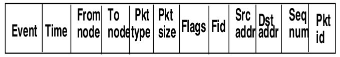 Figure-01: NS-2 trace file format (wired networks)
Structure of Trace Files
The following describe about the structure of the trace files produced for wired networks. The format of the trace files are different for wireless networks, and will be discussed in the Experiment on WiMax.
- The first field is event.It gives you four possible symbols '+' '-' 'r' 'd'. These four symbols correspond respectively to enqueued, dequeued, received and dropped.
- The second field gives the time at which the event occurs
- The third field gives you the input node of the link at which the event occurs
- The fourth field gives you the the output node at which the event occurs
- The fifth field shows the information about the packet type.i.e whether the packet is UDP or TCP
- The sixth field gives the packet size
- The seventh field give information about some flags
- The eight field is the flow id(fid) for IPv6 that a user can set for each flow in a tcl script.It is also used for specifying the color of flow in NAM display
- The ninth field is the source address
- The tenth field is the destination address
- The eleventh field is the network layer protocol's packet sequence number
- The last field shows the unique id of packet
Following are trace of two events:
r 1.84471 2 1 cbr 210 ------- 1 3.0 1.0 195 600
r 1.84566 2 0 ack 40 ------- 2 3.2 0.1 82 602

