Virtual Labs
IIT Kharagpur

Control Design via Pole Placement for an Inverted Pendulum on a Cart with Pre-Compensator Design

Virtual Labs
IIT Kharagpur

Control Design via Pole Placement for an Inverted Pendulum on a Cart with Pre-Compensator Design
Introduction:
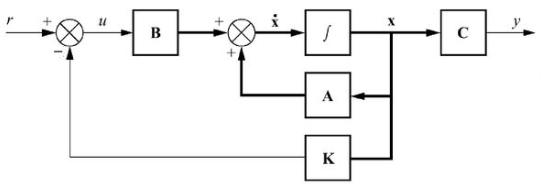
Linear time invariant system may be represented in state space form by the following equations:
State equation:
$$ \dot{x}(t)=A x(t)+B u(t) \tag{1a} $$
Output equation:
$$ y(t)= C x(t) \tag{1b} $$
where, x(t) is state vector, y(t) is output vector,
u is input or control vector, A is system matrix,
B is input matrix, C is output matrix.
The controller design for the state variable models involves feeding back all the state variables using appropriate weights to generate the error signal. State feedback allows arbitrary placement of roots of the closed-loop characteristic polynomial.
It is more powerful and offers greater flexibility than the output feedback that allows only selective placement of closed-loop roots. State feedback assumes that the complete set of state variables is available for feedback.
The pole placement design refers to the selection of feedback gains for placing the roots of the closed-loop characteristic polynomial at the desired locations in the complex plane.
The state feedback controller design refers to the selection of individual feedback gains for the complete set of state variables. It is assumed that all the state variables are available for observation.
The design goal is to improve the transient response of the system.
Controller design in state-space involves selection of suitable feedback gain vector (K) that imparts desired stability and performance characteristics to the closed-loop system.

