Theory:
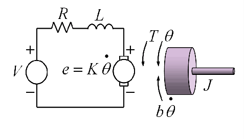
 Fig.1. DC Motor Model
The DC motor dynamics:
The DC motor dynamics are represted by the following equations:
Mechanical equation:
$$ J\ddot{\theta}(t)+b{\dot\theta}(t)=K V(t) \tag{1}$$
where,
J is the motor inertia,
b is the damping coefficient,
K is the motor constant,
θ(t) is the angular position of the motor,
V(t) is the input voltage (control input
u(t)).
Electrical equation:
$$ L \dot{i}(t)+R {i}(t)=u(t) \tag{2}$$
where,
L is the inductance,
R is the resistance,
i(t) is the motor current.
Transfer Function:
$$ G(s) = \frac{θ(s)}{u(s)} = \frac{K}{J s^2 + b s} \tag{3}$$
Linear time invariant system may be represented in state space form by the following equations:
State equation:
$$ \dot{x}(t)=A x(t)+B u(t) \tag{4a} $$
Output equation:
$$ y(t)= C x(t) \tag{4b} $$
Discrete state space form represented by the following equations:
State equation:
$$ {x}[k+1]=F x[k]+g u[k] \tag{5a} $$
Output equation:
$$ y[k]= C x[k] \tag{5b} $$
where,
Ts is the sampling time.
Adding Integral State for PID Control:
The integral state is defined as:
$$ x_3 [k+1]=x_3 [k]+e[k] $$
$$ x_3 [k+1]=x_3 [k]+(r[k]-y[k]) $$
$$ x_3 [k+1]=x_3 [k]+(r[k]- C x [k]) \tag{6} $$
where,
r[k] is the reference input,
e[k] is the error.
State Space Model of the DC motor:
Continuous State Space form:
$$ \begin{bmatrix} \dot{x}_1(t) \\ \dot{x}_2(t) \end{bmatrix} = \begin{bmatrix} 0 & 1 \\ 0 & -\frac{b}{J} \end{bmatrix} \begin{bmatrix} x_1(t) \\ x_2(t) \end{bmatrix} + \begin{bmatrix} 0 \\ \frac{K}{J} \end{bmatrix} u(t) \quad \tag{7} $$
where,
x1 is the position (
θ ),
x2 is the velocity,
u(t) is the input voltage,
y(t) is the output (position
θ ).
Discrete State Space form:
$$ \begin{bmatrix} x_1 [k+1] \\ x_2 [k+1] \end{bmatrix} = \begin{bmatrix} 1 & T_s \\ 0 & 1-\frac{b}{J} T_s \end{bmatrix} \begin{bmatrix} x_1 [k] \\ x_2 [k] \end{bmatrix} + \begin{bmatrix} \frac{K {T_s}^2}{2J} \\ \frac{K T_s}{J} (1-\frac{b T_s}{2J}) \end{bmatrix} u[k] \quad \tag{8}$$
Discrete State Space form with Integral state:
$$ \begin{bmatrix} x_1 [k+1] \\ x_2 [k+1] \\ x_3[k+1] \end{bmatrix} = \begin{bmatrix} 1 & T_s & 0\\ 0 & 1-\frac{b}{J} T_s & 0 \\ -1 & 0 & 1 \end{bmatrix} \begin{bmatrix} x_1 [k] \\ x_2 [k] \\ x_3[k] \end{bmatrix} + \begin{bmatrix} \frac{K {T_s}^2}{2J} \\ \frac{K T_s}{J} (1-\frac{b T_s}{2J}) \\ 0\end{bmatrix} u[k] \quad \tag{9} $$
Designing the State Feedback Controller:
Now that the discretized system with the integral state is available, the next step is to design the state feedback controller using pole placement. In this process, the objective is to determine the feedback gains that place the poles of the closed-loop system at desired locations for achieving the desired stability and performance.
The control law is:
$$ u[k] = - K x[k] + r[k] \tag{10} $$
where,
K = [
k1, k2, k3 ] is the state feedback gain matrix corresponding to the position, velocity, and integral error terms.
Using pole placement technique, compute the feedback gains that place the poles of the closed-loop system at desired locations.
This ensures that the closed-loop system behaves with the desired PID-like control:
Proportional control
Kp : Provided by
x1[
k] (position), that is (
k1 ),
Derivative control
Kd : Provided by
x2[
k] (velocity), that is (
k2 ),
Integral control
Ki : Provided by
x3[
k] (integral of the error) (
k3 ).


