
 Introduction
 Theory
 Simulation
 Self-evaluation
 Procedure
 Exercises
 References
Objectives
After completing this experiment you will be able to:
- Get familiar with the basics of satellite network and how to simulate them with ns2
- Learn the simulation of geostationary satellite and Iridium constellation with ns2
Time Required
Around 3.00 hours
Satellite
The word ‘Satellite’ comes from the Latin word ‘Satellit’ meaning an attendant, who is constantly revolving and attaining a larger body.Figure-01 shows a picture of satellite.
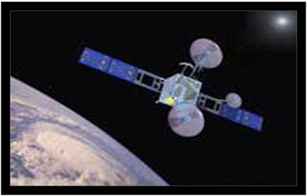 Figure-01: Picture of a Satellite
 A satellite is kept in a mathematical calculable path called orbit, around another planet to collect information or communication.Figure-02 shows different satellite orbits.Here two different types of satellite orbits[ii] are discussed namely, Geostationary Orbit and Low Earth Orbit.
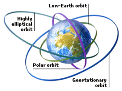 Figure-02: Types of Satellite Orbit
Geostationary Orbit
The rotational period of Geostationary Orbit is equal to that of earth. The geostationary satellite appear to be stationary from the earth surface as the earth and geostationary satellite move with the same speed. The orbit has zero inclination located directly above the equator (equatorial orbit ).
The geostationary earth orbit satellites are modelled by "bent pipe" repeaters which receives radio frequency by an uplink channel and piped to corresponding downlink[i].
Low Earth Orbit
A low earth orbit (LEO), circles close to the Earth. Generally, LEOs have altitudes between 500 and 2,000 km above the Earth’s surface. A special type of LEO is the Polar Orbit. The polar orbit is a LEO with a high inclination angle (close to 90degrees). So the LEO satellite move around the poles. Iridium and Teledesic are example of polar orbiting satellite systems and can be modelled in ns.
Courtesy: The following texts and ns codes are copied from the "The ns Manual, The VINT project, chapter-17 Satellite Networking in ns [i] ". For further details please refer the ns manual.
Simulating a Satellite network in ns2
we could introduce the following positions at the beginning of simulation script in order to correctly configure the terminals and satellite objects.
# Set these global options for the satellite terminals
global opt
set opt(chan)		Channel/Sat
set opt(bw_up) 		2Mb 		# uplink bandwidth
set opt(bw_down) 	2Mb 		# downlink bandwidth
set opt(phy) 		Phy/Sat
set opt(mac) 		Mac/Sat
set opt(ifq) 		Queue/DropTail
set opt(qlim) 		50		     # queue size (pkts)
set opt(ll)		LL/Sat
set opt(wiredRouting) 	OFF;
set opt(alt)            780;    # Polar satellite altitude (Iridium)
set opt(inc)            86.4;  	  # Orbit inclination w.r.t. Equator
Specifically, the array opt defines the type of the objects that make up a terminal node and configure their attributes. Then, configure the satellite object and terminals.
There are three different types of nodes in satellite network:
- Geostationary satellite nodes
- Terminal nodes (placed on the Earth's surface)
- Non-geostationary satellite nodes
Geostationary satellite nodes
A geostationary satellite is specified by its longitude above the equator. The longitude ranges from [-180,180] degrees. Two types of geostationary nodes exist: ``geo'' (for processing satellites) and ``geo-repeater'' (for bent-pipe satellites).
# Configure and create the satellite node “n1”
$ns node-config -satNodeType geo (or ``geo-repeater'') \
                -phyType Phy/Repeater \
		        -channelType $opt(chan) \
			    -downlinkBW $opt(bw_down) \
			    -wiredRouting $opt(wiredRouting)
set n1 [$ns node]
$n1 set-position $lon; # in decimal degrees
Terminal nodes
A terminal node[i] is specified by its latitude and longitude. Latitude ranges from [-90, 90] and longitude ranges from [-180, 180], with negative values corresponding to south and west, respectively.
# Configure and create the terminal node “n2”
$ns node-config -satNodeType terminal \
                -llType $opt(ll) \			#Link layer
                -ifqType $opt(ifq) \		#interface queue type
                -ifqLen $opt(qlim) \		#interface queue length
                -macType $opt(mac) \	 	#MAC type
                -phyType $opt(phy) \		#network interface type
                -channelType $opt(chan) \		#channel type
                -downlinkBW $opt(bw_down) \ 	#downlink bandwidth
                -wiredRouting $opt(wiredRouting)

set n2 [$ns node]
$n2 set-position $lat $lon;	# in decimal degrees
Polar orbiting satellite nodes(Non-geostationary satellite)
Satellite orbits are usually specified by six parameters: altitude, semi-major axis, eccentricity, right ascension of ascending node, inclination, and time of perigee passage.
The polar orbiting satellites in ns have purely circular orbits, so the orbits include parameters altitude, inclination, longitude, alpha and plane.
- Altitude is specified in kilometers above the Earth's surface.
- Inclination can range from [0.180]degrees with 90 corresponding to pure polar orbits and angles greater than 90 degrees corresponding to “retrograde'' orbits. The ascending node refers to the point where the footprint of the satellite orbital track crosses the equator moving from south to north. In this simulation model,
- Longitude of ascending node specifies the earth-centric longitude at which the satellite's nadir point crosses the equator moving south to north. Longitude of ascending node can range from [-180,180] degrees.
- Alpha, specifies the initial position of the satellite along this orbit, starting from the ascending node. For example, an alpha of 180 degrees indicates that the satellite is initially above the equator moving from north to south. Alpha can range from [0,360] degrees.
- Plane, is specified when creating polar satellite nodes- all satellites in the same plane are given the same plane index.
# Configure and create the polar orbitting satellite nodes “n3”
# Nodes 0-99 are satellite nodes; 100 and higher are earth terminals

$ns node-config -satNodeType polar \
		-llType $opt(ll) \		#Link layer
		-ifqType $opt(ifq) \		#interface queue type
		-ifqLen $opt(qlim) \		#interface queue length
		-macType $opt(mac) \		#MAC type
		-phyType $opt(phy) \		#network interface type
		-channelType $opt(chan) \	#channel type
		-downlinkBW $opt(bw_down) \	#downlink bandwidth
		-wiredRouting $opt(wiredRouting)

set alt $opt(alt)
set inc $opt(inc)

set n3 [$ns node]
$n3 set-position $alt $inc $lon $alpha $plane  #set the parameters
Satellite links
Satellite links[i] transmit and receive interfaces must be connected to different channels, and there is no ARP implementation in satellite links.
Network interfaces can be added with the following instproc:
$node add-interface $type $ll $qtype $qlim $mac $mac_bw $phy
The add-interface is eithere a add-gsl or add-isl. The following parameters must be provided:
- type: It is used to identify the different types of links: geo or polar for links from a terminal to a geo or polar satellite, respectively, gsl and gsl-repeater for links from a satellite to a terminal, and intraplane, interplane, and crossseam ISLs.
- ll:The link layer type (class LL/Sat is currently the only one defined).
- qtype:The queue type (e.g., class Queue/DropTail).
- qlim:The length of the interface queue, in packets.
- mac:The MAC type. Currently, two types are defined: class Mac/Sat- a basic MAC for links with only one receiver (i.e., it does not do collision detection), and Class Mac/Sat/UnslottedAloha- an implementation of unslotted Aloha.
- mac_bw:The bandwidth of the link is set by this parameter, which controls the transmission time how fast the MAC sends.
- phy:The physical layer- currently two Phys (Class Phy/Sat and Class Phy/Repeater) are defined. The class Phy/Sat just pass the information up and down the stack- as in the wireless code, a radio propagation model could be attached at this point. The class Phy/Repeater pipes any packets received on a receive interface straight through to a transmit interface.
An ISL(Inter Satellite Link) can be added between two nodes using the following instproc:
$ns add-isl $ltype $node1 $node2 $bw $qtype $qlim
This creates two channels, and appropriate network interfaces on both nodes, and attaches the channels to the network interfaces. The bandwidth of the link is set to bw. The linktype (ltype) must be specified as either intraplane, interplane, or crossseam.
A GSL(Ground to Satellite Link) involves adding network interfaces and a channel on board the satellite, and then defining the correct interfaces on the terrestrial node and attaching them to the satellite link, as follows:
$node add-gsl $type $ll $qtype $qlim $mac $bw_up $phy \
   [$node_satellite set downlink_] [$node_satellite set uplink_]
The type must be either geo or polar.The command setups a bidirectional connection between satellite node and the terminal node using parameters previously indicated opt.
Handoffs
Satellite handoff [i] modelling is used in LEO satellite network simulations.There are two types of links to polar orbiting satellites that must be handed off: GSLs to polar satellites, and crossseam ISLs.
Each terminal connected to a polar orbiting satellite runs a timer.when the time expires,the HandoffManager to check the current position of the satellite.If the satellite has fallen below the elevation mask of the terminal, the handoff manager detaches the terminal from that satellite's up and down links, and searches for another possible satellite. If it finds a suitable polar satelite, it connects its network interfaces to that satellite's uplink and downlink channels, and restarts the handoff timer. If it does not find a suitable satellite, it restarts the timer and tries again later. If any link changes occur, the routing agent is notified.
The elevation mask and handoff timer interval are set as follows:
HandoffManager/Term set elevation_mask_ 10; # degrees
HandoffManager/Term set term_handoff_int_ 10; # seconds
Handoffs may be randomized to avoid phase effects by setting the following variable:
HandoffManager set handoff_randomization_ 0; # 0 is false, 1 is true
If handoff_randomization_ is true, then the next handoff interval is a random variate picked from a uniform distribution across.
The satellite handoff interval is set by the following command:
HandoffManager/Sat set sat_handoff_int_ 10; # seconds
Interplane and crossseam ISLs are deactivated near the poles, because the pointing requirements for the links are too severe as the satellite draw close to one another. Shutdown of these links is governed by a parameter:
HandoffManager/Sat set latitude_threshold_ 70; # degrees
If crossseam ISLs exist, there are certain situations in which the satellites draw too close to one another in the mid-latitudes (if the orbits are not close to being pure polar orbits). The occurence of this orbital overlap is checked with the following parameter:
HandoffManager/Sat set longitude_threshold_ 10; # degrees
Routing
The routing genie[i] is a class SatRouteObject and is created and invoked with the following OTcl commands:
set satrouteobject_ [new SatRouteObject]
$satrouteobject_ compute_routes
where the call to compute_routes is performed after all of the links and nodes in the simulator have been instantiated.
Structure of trace files in Satellite network
The trace is organized in 16 fields as follows:
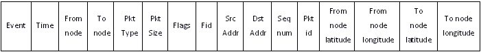
- The first 12 fields are similar to conventional ns tracing.
- The last four fields log the geographic latitude and longitude of the node logging the trace (the latitude and longitude correspond to the nadir point of the satellite).
Ex:
+ 1.0000 66 26 cbr 210 ------- 0 66.0 67.0 0 0 37.90 -122.30 48.90 -120.94
In this case, node 66 is at latitude 37.90 degrees, longitude -122.30 degrees, while node 26 is a LEO satellite whose subsatellite point is at 48.90 degrees latitude, -120.94 degrees longitude (negative latitude corresponds to south, while negative longitude corresponds to west).
To enable tracing of all satellite links in the simulator, use the following commands before instantiating nodes and links:
set f [open out.tr w]
$ns trace-all $f
Then use the following line after all node and link creation (and all error model insertion, if any) to enable tracing of all satellite links:
$ns trace-all-satlinks $f

