Virtual Labs
IIT Kharagpur

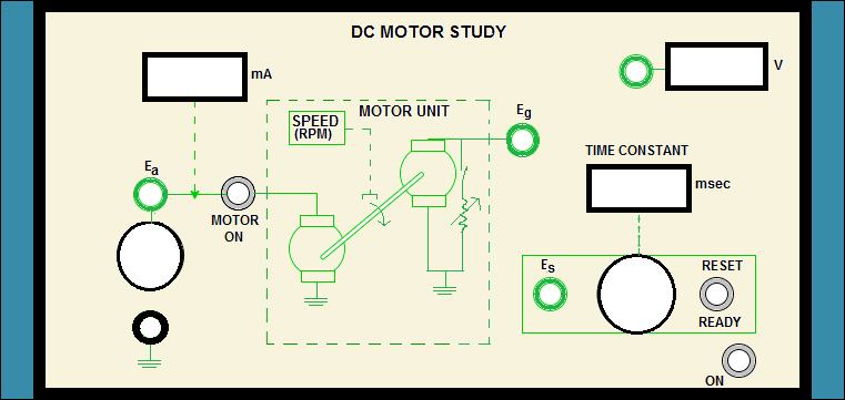
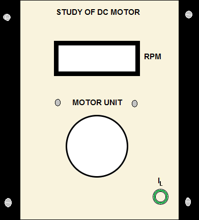
Study of DC Motor
Virtual Labs
IIT Kharagpur
Study of DC Motor

| Sl No. | Ea (volts) | Ia (mA) | N (rpm) | Eg (volts) |
|---|
| Sl No. | Load Step | Ia (mA) | N (rpm) | ω (rad/s) | Eb (volts) | Kb (volts/rad/s) | TM (newton-meter) |
|---|
| Sl No. | Ea (volts) | Eg (volts) | N (rpm) | Es (volts) | Time Constant (τm (msec)) | Gain Constant (KM (π N/30Ea)) |
|---|