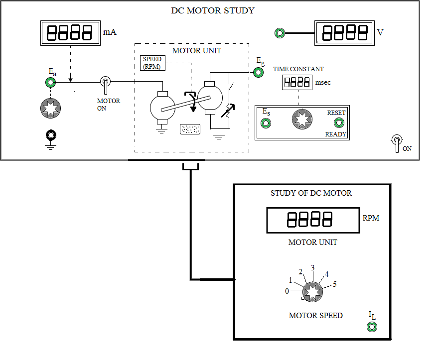
 Fig. 1. Panel drawing of the DC Motor plant
Steps to perform the simulation
Motor and Generator Characteristics
- First click on "Tests" button (Fig. 2) and click on 'No Load' to perform the experiment for finding the dc motor and generator characteristics.
- Click on 'ON' button to switch on the motor unit. Connect (blue dots for wire connection) 1-3 (Fig. 2).
- Note: Example: connection point 1 - connection point 2 (drag the wire from connection point 1 by pressing left mouse button and release on connection point 2).
- Click on 'Check Connection' button (Fig. 2).
- Note: Any wire connection can be deleted by clicking on the connected wire if required.
- Set 'MOTOR' switch to 'ON' by clicking on it.
- Set the 'RESET' switch to 'RESET'.
- Set load to 0 value.
- Apply armature voltage Ea through rotating knob1 (start with 3 volts).
- Note: To rotate any knob put the mouse cursor on the knob handle (blue line on the knob), a hand symbol will be showing. Press left mouse button, rotate clockwise to increase or anticlockwise to decrease values.
- Note: If the desired value does not appear while rotating the knob in one attempt, try rotating it back and forth to reach the correct value.
- Click on 'Simulate' button (Fig. 2). Observe motor armature current (mA), speed (rpm).
- Now click on the connected wire (1-3) to delete that and connect 2-3 (Fig. 2).
- Click on 'Check Connection' button.
- Click on 'Simulate' button. Observe generator voltage Eg.
- Click on 'Table' button to get the observation table.
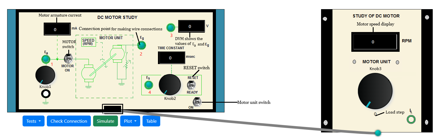 Fig. 2. DC Motor plant simulation model
- Delete connection 2-3 and again connect 1-3, click on 'Check Connection' button then on 'Simulate' button. Increase the armature voltage to 4 volts and follow
step 3.
- Vary Ea from 5 - 12 volts and follow step 3.
- Now Click on 'Plot' button, then on 'Speed (N) Vs. Motor armature voltage (Ea)'.
- From a slope of the plot calculate motor constant KM (rpm/volts) (calculation explained in theory).
- Again click on 'Generator voltage (Eg) Vs. Speed (N)' under plot button.
- From a slope of this plot calculate generator constant KG (volts/rpm) (calculation explained in theory).
- Plots can be downloaded by clicking on 'Download Plot' button.
- Now enter the values of KM and KG in the corresponding box under 'Result Block'.
- Bring back all the knobs to zero value. Set 'MOTOR' switch to 'OFF' by clicking on it again and switch off the motor unit.
Torque-Speed Characteristics
- First click on "Tests" button and click on 'Load' to perform the experiment for finding the dc motor torque-speed characteristics.
- Click on 'ON' button to switch on the motor unit.
- Connect 1-3, click on 'Check Connection' button. set 'MOTOR' switch to 'ON' by clicking on it.
- Set the 'RESET' switch to 'RESET'. Set load to 0 value.
- Apply armature voltage Ea through knob1 and set Ea to 6 volts.
- Click on 'Simulate' button. Observe motor armature current (mA), speed (rpm).
- Now click on the connected wire (1-3) to delete that and connect 2-3 , click on 'Check Connection' button then on 'Simulate' button. Observe generator voltage Eg.
- Click on 'Table' button to get the observation data.
- Set load to 1 through knob3. Delete connection 2-3 and again connect 1-3. Click on 'Check Connection' button.
- Click on 'Simulate' button and follow step 3. Now vary the load from 2 to 5 through knob3 and take observations following step 3.
- Click on 'Check Connection' button then on 'Simulate' button each time after a wire connection is made.
- Click on 'Plot' then click on 'Torque (TM) Vs. Speed (N)'.
- Now from a slope of the plot calculate viscous friction coefficient B (newton-meter/rad/sec) of motor and calculate average value of motor back emf constant Kb
(volts/rad/sec) from the observation table.
- Now enter the values of B and Kb in the corresponding box under 'Result Block'.
- Bring back all the knobs to zero value.
- Follow steps 1-4 for Ea = 8, 10 and 12 volts.
- Set 'MOTOR' switch to 'OFF' by clicking on it again and switch off the motor unit.
Step Response of Motor
- First click on "Tests" button and click on 'Step Response' to perform the experiment for finding the dc motor transfer function.
- Click on 'ON' button to switch on the motor unit.
- Connect 1-3, click on 'Check Connection' button, set 'MOTOR' switch to 'ON' by clicking on it.
- Set the 'RESET' switch to 'RESET'. Set load to 0 value.
- Apply armature voltage Ea through knob1 and set Ea to 8 volts. Click on 'Simulate' button.
- Observe motor armature current (mA), speed (rpm).
- Now click on the connected wire (1-3) to delete that and connect 2-3 , click on 'Check Connection' button then on 'Simulate'.
- Observe generator voltage Eg
- Now delete connection 2-3 and connect 4-3 , click on 'Check Connection' button then on 'Simulate' to observe Es value in DVM.
- Set Es through knob2 to 63.2 % of Eg (measured above).
- Set 'MOTOR' switch to 'OFF'. Set 'RESET' switch to 'READY'.
- Now set the 'MOTOR' switch to 'ON', click on 'Simulate' and observe the 'Time Constant (msec)'.
- Click on 'Table' to get the observation data. Observe the step response.
- Now find the motor inertia J using the values of B, Kb (calculated before) and τm from observation table following the formula provided in 'Result Block'.
- Now enter the value of J in corresponding box under 'Result Block'.
- Click on 'Show Transfer Function' button to get the transfer function of the motor.
- Bring back all the knobs to zero value. Follow steps (1-6) for Ea= 10 and 12 volts. Set 'MOTOR' switch to 'OFF' and switch off the motor unit..