

Modeling UML Use Case Diagrams and Capturing Use Case Scenarios
Use case diagrams belong to the category of behavioural diagram of UML diagrams. Use case diagrams aim to present a graphical overview of the functionality provided by the system. It consists of a set of actions (referred to as use cases) that the concerned system can perform, one or more actors, and dependencies among them.
An actor can be defined as an object or set of objects, external to the system, which interacts with the system to get some meaningful work done. Actors could be human, devices, or even other systems.
For example, consider the case where a customer withdraws cash from an ATM. Here, customer is a human actor.
Actors can be classified as below, [1] :
A use case is simply a functionality provided by a system.
Continuing with the example of the ATM, withdraw cash is a functionality that the ATM provides. Therefore, this is a use case. Other possible use cases includes, check balance, change PIN, and so on.
Use cases include both successful and unsuccessful scenarios of user interactions with the system. For example, authentication of a customer by the ATM would fail if he enters wrong PIN. In such case, an error message is displayed on the screen of the ATM.
Subject is simply [3] the system under consideration. Use cases apply to a subject. For example, an ATM is a subject, having multiple use cases, and multiple actors interact with it. However, one should be careful of external systems interacting with the subject as actors.
An actor is represented by a stick figure and name of the actor is written below it. A use case is depicted by an ellipse and name of the use case is written inside it. The subject is shown by drawing a rectangle. Label for the system could be put inside it. Use cases are drawn inside the rectangle, and actors are drawn outside the rectangle, as shown in figure - 01.
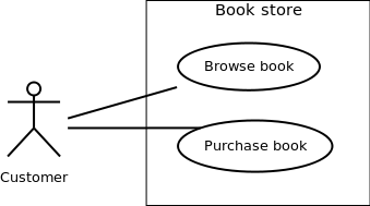
Figure - 01: A use case diagram for a book store
A use case is triggered by an actor. Actors and use cases are connected through binary associations indicating that the two communicates through message passing.
An actor must be associated with at least one use case. Similarly, a given use case must be associated with at least one actor. Association among the actors are usually not shown. However, one can depict the class hierarchy among actors.
Three types of relationships exist among use cases:
Here, instead of identifying objects one goes for identification of classes based on some similar characteristics. These are the specialized classes. Common characteristics are taken from them to form the higher level generalized classes.
Include relationships are used to depict common behaviour that are shared by multiple use cases. This could be considered analogous to writing functions in a program in order to avoid repetition of writing the same code. Such a function would be called from different points within the program.
For example, consider an email application. A user can send a new mail, reply to an email he has received, or forward an email. However, in each of these three cases, the user must be logged in to perform those actions. Thus, we could have a login use case, which is included by compose mail, reply, and forward email use cases. The relationship is shown in figure 02.
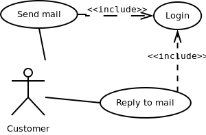
Figure - 02: Include relationship between use cases
Include relationship is depicted by a dashed arrow with a «include» stereotype from the including use case to the included use case.
Use case extensions are used used to depict any variation to an existing use case. They are used to the specify the changes required when any assumption made by the existing use case becomes false [4, 5].
Let's consider an online bookstore. The system allows an authenticated user to buy selected book(s). While the order is being placed, the system also allows to specify any special shipping instructions [8], for example, call the customer before delivery. This Shipping Instructions step is optional, and not a part of the main Place Order use case. Figure - 03 depicts such relationship.
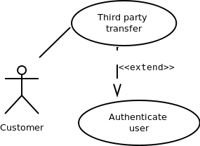
Figure - 03: Extend relationship between use cases
Extend relationship is depicted by a dashed arrow with a «extend» stereotype from the extending use case to the extended use case.
Generalization relationship are used to represent the inheritance between use cases. A derived use case specializes some functionality it has already inherited from the base use case.
To illustrate this, consider a graphical application that allows users to draw polygons. We could have a use case draw polygon. Now, rectangle is a particular instance of polygon having four sides at right angles to each other. So, the use case draw rectangle inherits the properties of the use case draw polygon and overrides it's drawing method. This is an example of generalization relationship. Similarly, a generalization relationship exists between draw rectangle and draw square use cases. The relationship has been illustrated in figure - 04.
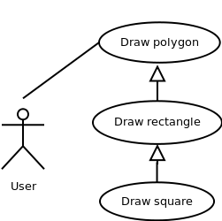
Figure - 04: Generalization relationship among use cases
Generalization relationship is depicted by a solid arrow from the specialized (derived) use case to the more generalized (base) use case.
Given a problem statement, the actors could be identified by asking the following questions:
Once the primary and secondary actors have been identified, we have to find out their goals i.e. what are the functionality they can obtain from the system. Any use case name should start with a verb like, "Check balance".
Following general guidelines could be kept in mind while trying to draw a use case diagram:
Also look at [9] for further tips.