
- Learn about clamper circuits
- Positive Clamper
- Negative Clamper
- Biased Positive Clamper
- Biased Negative Clamper
What are Clampers?
Clamper shift an input signal by an amount defined by an independent voltage source. Clampers are also known as dc restorers or clamped capacitors.
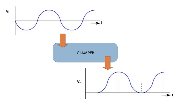
Figure:1
Types of Clampers
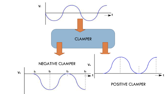
Figure:2
Positive Clamper
Positive clamping circuit clamps the input signal to the +ve DC level i.e. above the zero level.
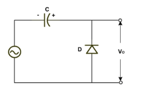
Figure:3
Positive Clamper: -ve Half Cycle
During the negative half cycle of the input signal , diode is forward biased , thus conducts and acts like a short circuit. The output voltage Vo=>0 volts. The capacitor is charged to the peak value of input voltage Vmand it behaves like a battery (DC source of magnitude Vm).
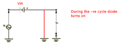
Figure:4
Positive Clamper :+ve Half Cycle
During the positive half of the input signal,the diode does not conduct and acts as an open circuit . Capacitor can only discharge through the R(Load ). Since RL has high resistance, the capacitor discharges very little each period.
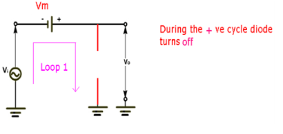
Figure:5
Positive Clamper – Circuit Analysis
Applying KVL across loop 1(KVL at maximum positive input ,vin=+Vm), Vin + Vm — Vout =0 .Hence the output voltage,Vout: Vin (peak)+Vm=Vm + Vm . This gives a positivelyclamped voltage. Vo =Vm+ Vm = 2 Vm
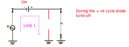
Figure:6
Positive Clamper — Waveform
A diode clamper adds a DC level to an AC voltage. The capacitor charges to the peak of the supply minus the diode drop. Once charged, the capacitor acts like a battery in series with the input voltage. The AC voltage will “ride" along with the DC voltage. The polarity arrangement of the diode determines whether the DC voltage is negative or positive.
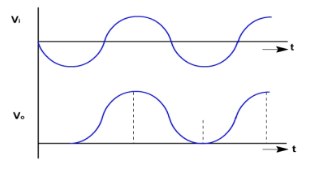
Figure:7
Negative Clamper
Negative clamping circuit clamps the input signal to the –ve DC level i.e. below the zero level
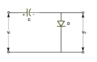
Figure:8
Negative Clamper :+ve Half Cycle
During the positive half cycle the diodes conducts and acts like a short circuit . The capacitor charges to peak value of input voltage Vm . During this interval the output Vo which is taken across the short circuit will be zero .
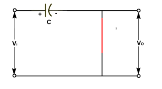
Figure:9
Negative Clamper : -ve Half Cycle
During the negative half of the input signal , the diodes does not conduct and acts as an open circuit.
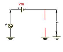
Figure:10
Negative Clamper – Circuit Analysis
The output voltage can be found by applying KVL (KVL at maximum negative input , Vin=-Vm). Vm-Vm-Vo=0 Vo=-2Vm
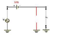
Figure:11
Negative Clamper – Waveform
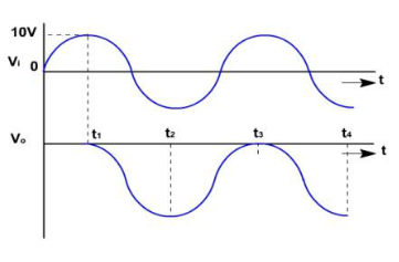
Figure:12
Exploratory Test
What will be the output of the POSITIVE Clamper circuit shown if the shown input waveform is given?
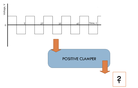
Figure:13
Exploratory Test
During the positive half of the input signal , the diode not conduct and acts as an open circuit . Capacitor can only discharge through the R(load).If the load resistance is small- such that Time constant =2*time period of input waveform. How will the output waveform look like ?
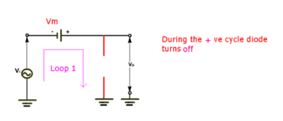
Figure:14
Biased Clampers – Until Now
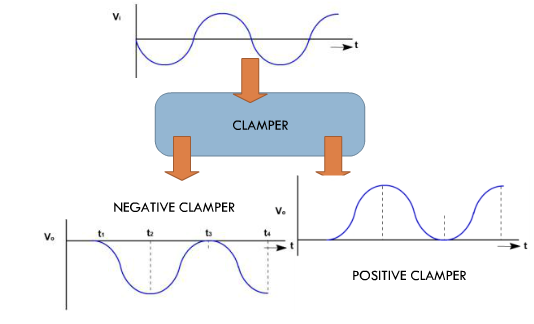
Figure:15
Biased Clampers – Add a higher DC
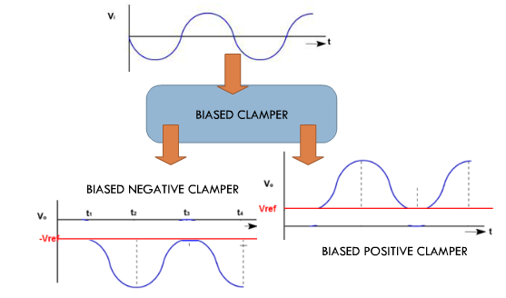
Figure:16
Biased Clamper
A biased clamper allows a waveform to be shifted above (or below) a dc reference other than 0 V. By using a voltage source and resistor, the clamper can be biased to bind the output voltage to a different value. The voltage supplied to the resistor will be equal to the offset from 0.7v (assuming an Si diode) in the case of either a positive or negative clamper — the clamper type will determine the direction of the offset.
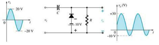
Figure:17
Slides: Diodes as Clampers
pdf: Theory of Diodes as Clamper

Construct the circuit as below:
- Use AC source of 5Volt from function generator , 1KHz
- Use a Diode and Capacitor of 100mF . Use Load of 5.1KOhms
- Connect Oscilloscope as shown
- Run simulation and observe output waveforms
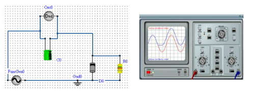
Figure:1
Negative Clamper :Experiment
Construct the circuit as below:
- Use AC source of 5Volt from function generator , 1KHz
- Use a Diode and Capacitor of 100mF . Use Load of 5.1KOhms
- Connect Oscilloscope as shown
- Run simulation and observe output waveforms
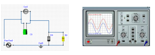
Figure:2
Positive Biased Clamper: Experiment
Construct the circuit as below:To apply a bias of 2V
- Use AC source of 5Volt from function generator , 1KHz
- Use a Diode and Capacitor of 100mF and Load of 5.1 KOhms
- Connect DC source of 3V as shown
- Connect Oscilloscope as shown
- Run simulation and observe output waveforms being clamped at a higher value as expected.
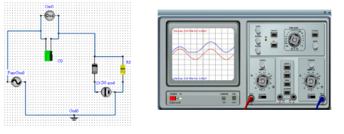
Figure:3
Slides: Diodes as Clampers
pdf: Procedure of Diodes as Clamper


Test Your Knowledge!!
