
Virtual Lab on Robotics and Control
Sponsored by Ministry of Human Resource and Development, INDIA.Indian Institute of Technology Kharagpur


Sponsored by Ministry of Human Resource and Development, INDIA.Indian Institute of Technology Kharagpur
To study the open loop characteristics of DC motor and experiment it with Matlab simulation File
The electric circuit of the armature and the free body diagram of the rotor for the DC motor are shown in the following figure:
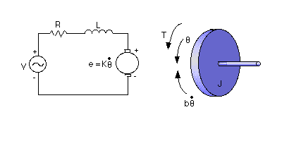
The motor torque, T, is related to the armature current, i, by a constant factor. The back emf, e, is related to the
rotational velocity by the following equations:
In SI units, (torque constant) is equal to
(Motor constant).Put,
=
= K

From the figure above we can write the following equations based on Newton's law combined with Kirchhoff's law:

The time-domain model for dc motor is given below:
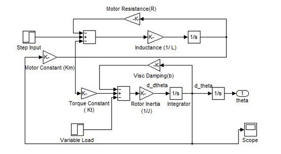
The transfer function of the dc motor system is given by:

The block diagram of dc motor in s-domain is given below:

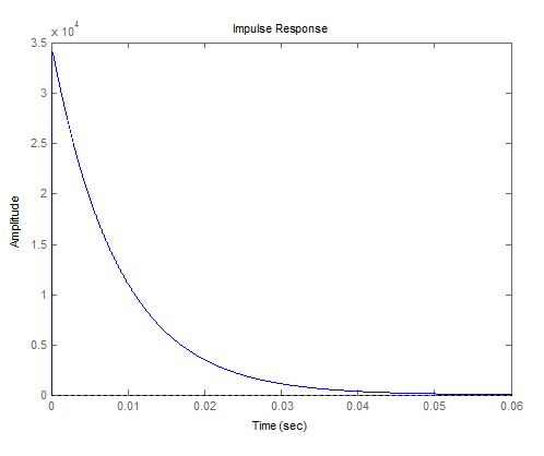
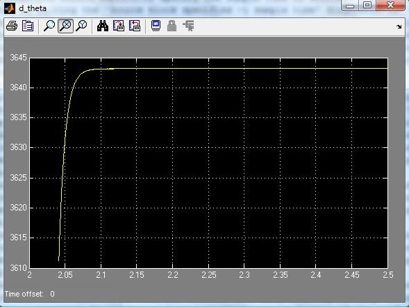
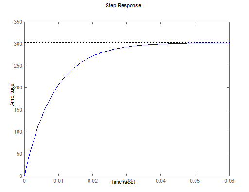
The step response for an open loop dc motor system is given below.
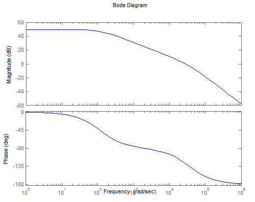
The Bode diagram of the system is shown in the figure below:
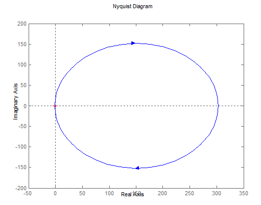
The Nyquist diagram of the system is shown in the figure below:
The DC motor model for open loop step response and impulse response can be created using Matlab/Simulink.
PLEASE NOTE THAT THE MATLAB/SIMULINK VERSION USED IS 7.10.0.499 (R2010a)
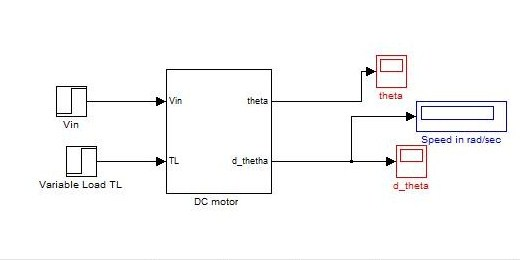
The images of the models along with the corresponding speed profiles are given below.
Simulink Model for Open loop impulse response of DC motor:
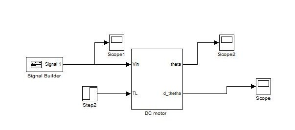
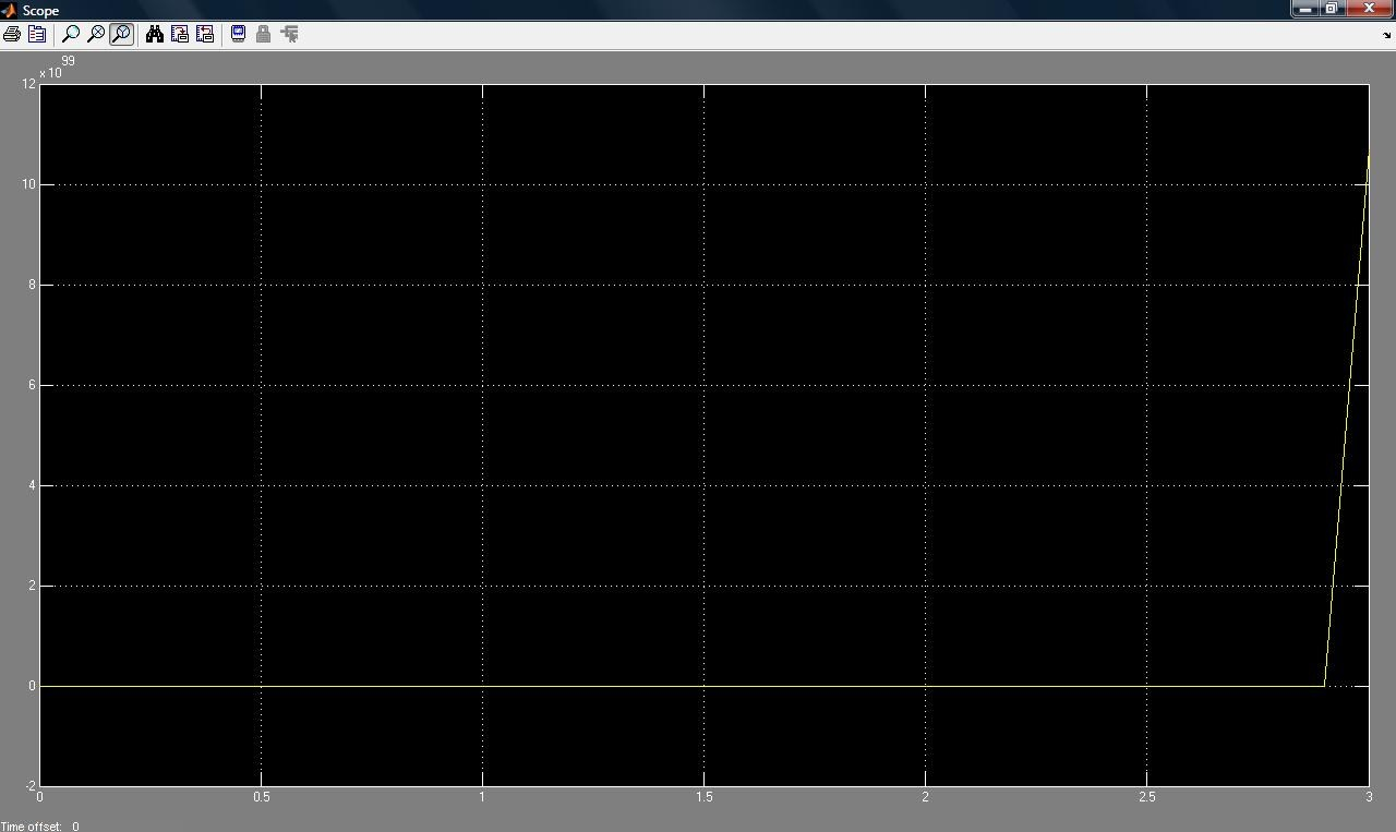
Simulink Model for Open loop step response of DC motor:
