CLOSED LOOP CHARACTERISTICS OF DC MOTOR
PROPORTIONAL-DERIVATIVE-INTEGRAL CONTROL (CONTINUOUS-TIME)
A Proportional-Integral-Derivative controller (PID controller) is a generic controller widely used in industrial control systems.
The PID control equation involves three separate parameters; the Proportional, the Integral and Derivative terms. The Proportional
term responds instantaneously to the current error (providing instantaneous response). The Integral term responds to the
accumulation of errors (providing a slow response that drives the steady-state error towards 0). And the Derivative term responds
to the rate at which the error is changing (providing some anticipatory response). Their respective weighting determines the
controls response.

A block diagram of a PID controller
Proportional Action
Proportional action provides an instantaneous response to the control error. This is useful for improving the response of
a stable system but cannot control an unstable system by itself. Additionally, the gain is the same for all frequencies leaving
the system with a nonzero steady-state error.
Integral Action
Integral action drives the steady-state error towards zero but slows the response since the error must accumulate before a
significant response is output from the controller. Since an integrator introduces a system pole at the origin, an integrator
can be detrimental to loop stability. Only controllers with integrators can wind-up where, through actuator saturation, the
loop is unable to comply with the control command and the error builds until the situation is corrected.
Derivative Action
Derivative action acts on the derivative or rate of change of the control error. This provides a fast response, as opposed to
the integral action, but cannot accommodate constant errors (i.e. the derivative of a constant, nonzero error is zero).
Derivatives have a phase of +90 degrees leading to an anticipatory or predictive response. However, derivative control will
produce large control signals in response to high frequency control errors such as set point changes (step command) and
measurement noise.
In order to use derivative control the transfer functions must be proper. This often requires a
pole to added to the controller.
A PID controller can be used in ideal as well as standard form.
Ideal versus standard PID form
The form of the PID controller most often encountered in industry, and the one most relevant to tuning algorithms is the standard form.
In this form the

gain is applied to the

, and

terms, yielding:

where

is the integral time and

is the derivative time.
In the ideal parallel form, shown in the controller theory section:

where the gain parameters are related to the parameters of the standard form through

=

/

and

=


.
This parallel form, where the parameters are treated as simple gains, is the most general and flexible form. However, it is
also the form where the parameters have the least physical interpretation and is generally reserved for theoretical treatment
of the PID controller. The standard form, despite being slightly more complex mathematically, is more common in industry.
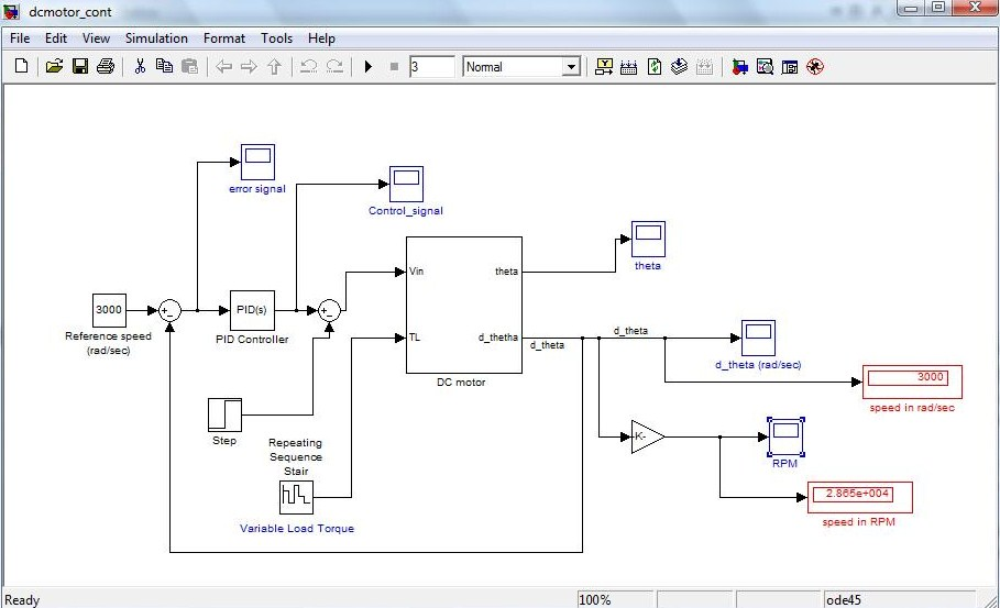
In the Matlab/Simulink model of
PID Control given below, we have used Ideal PID Controller in
continuous time.
PID continuous
PLEASE NOTE THAT THE MATLAB/SIMULINK VERSION USED IS 7.10.0.499 (R2010a)
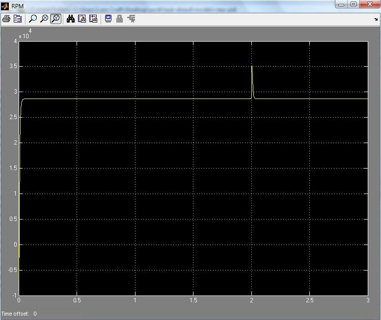
The images of the model along with the corresponding speed profile are given below.
Simulink Model for PID control(continuous time) of DC motor system:


