

Virtual Lab on Robotics and Control
Sponsored by Ministry of Human Resource and Development, INDIA.Indian Institute of Technology Kharagpur


Sponsored by Ministry of Human Resource and Development, INDIA.Indian Institute of Technology Kharagpur
Mechanisms are used in variety of fixed motion generation applications in Engineering, where as Robots are used in applications where programmable motion in required.
This Laboratory provides a basic exposure to design and control of such motion control applications in various applications. Ranging from 2D planar mechanisms to that
of spatial mechanism design a set of experiments are offered concerning position, velocity and acceleration synthesis and analysis for basic motions. In addition some
basic mechatronic control methods using a common Lab PC and USB interface to control motion generating devices like stepper motor and servo motor are offered. These
are further augmented with real robot control as applied in fixed base manipulators to that of moving base robots.
To show how a motion path in a 6-D space that can be generated by an open chain mechanism or robot using 5 inputs.
The motion of the end-effector (or the tool) of the robot can be mapped to that of the inputs given. However it will be shown that all types of motions cannot be generated - the manipulation space is limited.
User learns the various aspects of motions generated in such mechanism or robot through a series of visual simulations that can be carried out by varying its basic parameters.
MOVEMASTER RM-501
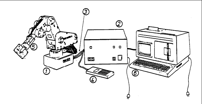
The Mitsubishi Movemaster RM-501 robot is a robotic arm with five rotational joints. These are actuated with DC motors to each of which two encoders are associated which allow differential directional information to be read for each joint.
The overall size of the robot is comparably small with a circular work envelope of 445mm maximum horizontal reach and a maximum payload of 1.2kg.
In addition to the robot itself, the complete robotic system for the Mitsubishi Movemaster consists of several components, which are shown in the following Figure:
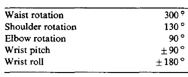
Robot kinematics involves computing the end effector's position from the joint angles and vice versa for controlling the position of robot.
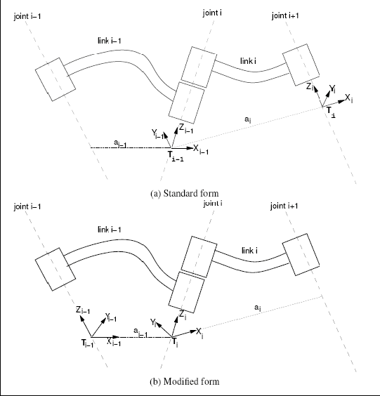
Forward kinematics involves computing the position and orientation of the end effecter from the joint angles. The forward kinematics of a kinematic chain can be established by defining a coordinate system at the root of each link and then defining transformation matrices between subsequent coordinate systems as:

For rotational joints, each matrix will then contain the joint angle θn as a variable.
The overall transformation from the earth fixed reference frame to the end effecter fixed reference frame is then given by

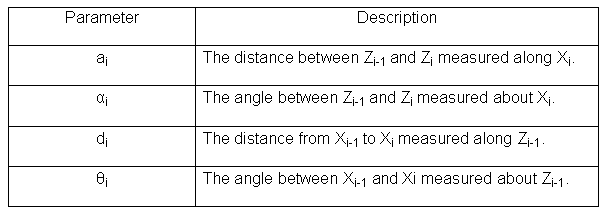
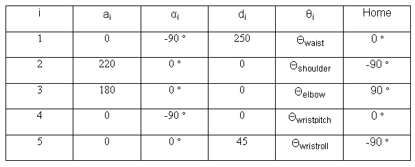
 the Denavit-Hartenberg matrix contains four parameters that fully define coordinate transformation from the coordinate system attached to the
previous link to the coordinate system attached to the next link. The four parameters and a description of their meaning is given in Table
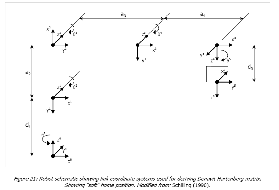

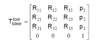
This matrix can be understood as being composed of a vector p defining the position the end effecter in space, and a 3 by 3 matrix R defining
the orientation of the end effecter:
The page shows the figure after simulation and updates the image with the last figure
The page shows the animation through a series of figures by incrementally increasing the angle using Java Session