
Virtual Labs
IIT Kharagpur

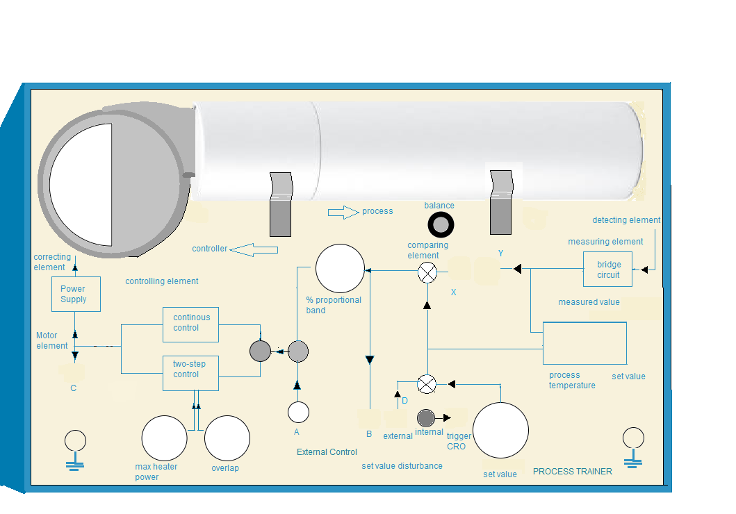
Study and Operation of the Process Trainer Setup
Virtual Labs
IIT Kharagpur
Study and Operation of the Process Trainer Setup


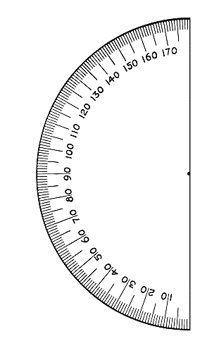


| Sl No. | Blower Angle (°) | Distance (mm) | Transport Lag (ms) | Transfer Lag (ms) |
|---|