Introduction
Engineering is concerned with understanding and controlling the materials and forces of nature for the benefit of humankind. Control system is concerned with understanding and
controlling segments of the environment, often called systems, to provide useful economic products for society. The twin goals of understanding and controlling are complementary because
effective systems control requires that the systems to be understood and modeled.
In today's era the present challenges are the modeling and control of modern, complex, interrelated systems such as traffic control systems, chemical processes, robotic systems,useful and interesting industrial automation systems.
Perhaps the most characteristic quality of control engineering is the opportunity to control machines and industrial and economic processes for the benefit of society.
Control engineering is based on the foundations of feedback theory and linear system analysis, and it integrates the concepts of network theory and communication theory.
Therefore control engineering is not limited to any engineering discipline but is equally applicable to aeronautical, chemical, mechanical, environmental, civil, and electrical engineering.
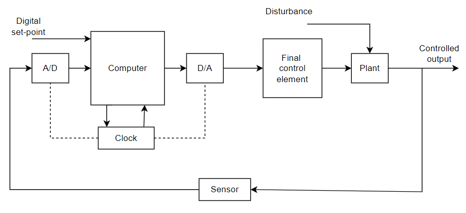
A digital control system uses digital hardware, usually in the form of a programmed digital computer, as the heart of the controller. The following block diagram shows the simple block diagram of a digital control system.
 Fig. 1. Basic block diagram of a digital control system
In most cases, the measuring transducer (sensor) and the actuator (final control element) are analog devices, requiring, respectively, analog-to-digital (A/D) and digital-to-analog (D/A) conversion at the computer input and output.
There are, of course, exception; sensors which combine the function of the transducer and the A/D converter, and actuators which combine the function of the D/A converter and the final control element are available.
In most cases, however, our sensors will provide an analog voltage output, and our final control elements will accept an analog voltage input.
The A/D converter performs the sampling of the sensor signal (analog feedback signal) and produces its binary representation.
The digital computer (control algorithm) generates a digital control signal using the information on desired and actual plant behavior.
The digital control signal is then converted to analog control signal via the D/A converter. A real-time clock synchronizes the actions of the A/D and D/A converters, and shift registers.
The analog control signal is applied to the plant actuator to control the plant's behavior.
The overall system is hybrid in nature; the signals are in the samples form (discrete-time signals) in the computer, and in a continuous form in the plant.
Such systems have traditionally been called sampled-data systems; we will use this term as a synonym for compuer control systems/digital control systems.
Objective of the laboratory:
In this laboratory, students will get to explore and learn various concepts regarding Digital Control Systems and different experiments.
The experiments are developed on open-source web-based platforms, so the student doesn't need to download or install any third-party applications.
Each experiment is designed in such a way that the student first gets to learn the theories well and then performs the experiment to enhance their knowledge.
This laboratory contains 10 experiments, through which students learn different control techniques.


