
Objective:
To Verify the Compensation Theorem.
In a linear time invariant network when the resistance `(R)` of an uncoupled branch, carrying current `(I)`, is changed by `ΔR_L` , the currents in all the branches would change and can be obtained by assuming that an ideal voltage source of `V_c` has been connected such that `V_c=IΔR_L` in series with `R+ΔR_L` when all other sources in the network are replaced by their internal resistances.
Explanation :
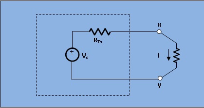
Let us assume a load `R_L` connected to a dc source network whose thevenin's equivalent gives `V_o` as the Thevenin's voltage and `R_(Th)` as Thevenin resistance.

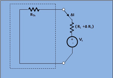
Let the load resistance `R_l` be changed to `R+ΔR_L`.Since the rest of the circuit remains unchanged,the Thevenin equivalent network remains the same.This Change of current being termed as Δ`I` , we find
Δ`I=I'-I`
`=V_o/(R_(Th)+R_L+ ΔR_L) - V_o/(R_(Th)+R_L)`
`=(V_o(-ΔR_L))/((R_(Th)+R_L)(R_(Th)+R_L+ΔR_L))`
`=-V_c/(R_(Th)+R_L+ΔR_L).........(3)`
`V_c=I*ΔR_L`
This voltage `V_c` is termed as compensating voltage.

[Fig.1 The circuit diagram for verification of Compensation Theorem]
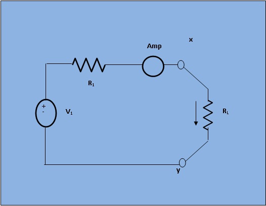
case 1: Set the voltage (say V1=100V), internal resistance (say Rint=50ohm) and load resistance (RL). Simulate the circuit and observe the current I.
case 2: Change RL by ΔRL. ΔRL can change upto `+-2%` of RL. Simulate the circuit and observe the load current (I').
case 3: Simulate the circuit. Observe the varying current (difference between case 1 and case 2) in compensating circuit.

Minimum System Requirement:
- A standard PC running Microsoft Windows XP, Windows Vista.
- 512MB RAM and 500 MB of available hard-disk space is recommended
- 1024x768 or higher screen resolution;
- a mouse or other pointing device
- A CD-ROM drive

The simulator for this experiment is designed based on JavaScript platform combined with HTML5 Canvas for graphics. So the users are recommended to use browsers with HTML5 compatible.
Link to the simulator:
Click here to perform the Experiment

Quizzes content coming soon.

A) Book Name:
Book Name:
1) A. Chakrabarti, Circuit Theory (Analysis and Synthesis). Fifth Edition : 2006, Dhanpat Rai and Co.
2) A. Bruce Carlson, Circuits. First Reprint :2002, Thomson Asia Pte Ltd.
3) Parker Smith, Problems in Electrical Engineering. Ninth Edition :2003 , M/s Constable and Company, London.
B) Video Lecture:
Click here for NPTEL Video Lecture