1) What is the basic philosophy of the working of an Impulse Current Generator (ICG)?
High magnitude Impulse currents are produced by charging a bank of capacitors connected in parallel, and discharging them through a series R-L circuit with a suitable triggering gap. ‘R’ can be the dynamic resistance of the test object or the resistance included in the circuit. ‘L’ is an air cored inductor.
2) Comment on the wave shape with a description of their front and tail time
Impulse currents are produced to test surge diverters on transmission lines. The waveshapes used in testing are 4/10 μs and 8/20 μs pulse. It follows a standard which states, for a 4/10 μs pulse, the wave front time is 4 μs and wave tail time is 10 μs. The tolerances allowed in these are ±10 % only.
3) Why are air cored inductors preferred over the other types of inductors?
Air cored reactors are generally used as a short circuit limiting impedance. When combined with a capacitor of suitable value, it can be used as a harmonic filter at all voltage levels of the power system. The insulation in air cored inductors is air or fiber glass. Despite the low cost, air cored reactors perform well under high frequencies, which would saturate a solid core.
4) Name the IEC specification which deals with the generation of impulse currents
Generation of impulse currents is dealt with, in IEC 60060-1 and IEC 60099-4. The measurement, evaluation and analysis of impulse voltages and impulse currents can be performed according to IEC 61083, IEC 60060, IEC 60076, IEC 60099 and IEC 60230, the relevant standards for high voltage impulse testing.
A detailed description of all the standards can be found at
http://www.iec.ch/
5) What is critical resistance of an impulse generation circuit?
The output waveform depends on the magnitude of the damping resistor. If the magnitude of the resistor is large, energy is lost as heat and thus a decrease in the magnitude of the output pulse is achieved. Critical resistance is defined as the minimum resistance below which the output waveform is a bipolar pulse which converges to ‘0’ after infinite time. If summation of the all the resistances in the circuit [∑ (Rcircuit)] is less than the critical resistance, a damped sine waveform is achieved. The damping can be increased by increasing the test sample resistance by some means. If ∑ (Rcircuit) is equal or more than the critical resistance then an unipolar current pulse is obtained which converges to ‘0’ after a very long time. The critical resistance of the network is calculated using equation (1).
Rc=
6) How is the peak amplitude of the impulse current varied?
The circuit elements of an impulse current generator should be modeled with care. The two components which are responsible for having an effect on the output current are resistance and inductance. The decrease in resistance allows more current to flow and a decrease in inductance offers less resistance to the change in current and thus building up the front time. On the other hand, when the inductance of the circuit is high, it offers greater opposition to the change in current, thus providing a sluggish response on the output impulse current pulse. On the other hand, both the above mentioned components cannot have very low values, as the circuit will be devoid of damping. The output pulse oscillates for a very long time before converging at ‘0’.
7) What is the effect of larger inductances on the circuit?
Inductances offer opposition to rapid change in current in any circuit. High values of inductances distort the output waveform at its peak due to the prevailing LC oscillations. The value of the capacitance is a measure of the surge capacity of the network. And care should be taken to look into the discharge class of the test object(s) before designing the inductor.
8) What type of impulse currents are surge protectors subjected to?
Surge protectors have to operate irrespective of the polarity of the surge, i.e. the surge arrester is subjected to a bipolar impulse current signal as discussed in Q.6.
9) How does the output waveform of the impulse current generator depend on the impedance of the test sample?
The resistors along with the inductors and the impulse capacity influence the waveform of the impulse current significantly. If the impedance of the test sample is much lower than the impedance of the rest of the circuit put together, the impulse generator will effectively act as an ideal current source supplying charging current. The waveform greatly depends on the linearity of the load. Generally, Metal Oxide Varistors (MOV’s) are non linear loads. So, the waveform may not follow a standard claimed waveform. For effective test procedure in the laboratory, it is essential to know the relation between the load impedance and the other impedances before charging the circuit.
10) What kind of stress does an impulse current produce on the test sample?
Lightning strikes induce High voltage and High current pulses into the power system. High current pulses test the thermal insulation capability of the test sample. Therefore, the test sample is subjected to extreme thermal test conditions by subjecting it to Impulse currents of very high magnitudes.
11) What are the applications of long duration impulse current pulses?
Lightning is phenomenon which occurs with a random probability. They are generally followed by re-strikes at the same point. Due to consecutive re-strikes, the arrester may fail, although, it provided complete insulation for the first strike. This is because, a small portion of the surge might leak through the arrester into the main circuitry, and even a very small magnitude of the lightning surge is good enough to damage some expensive electronic components like diodes/ thyristors. Long impulse current pulses basically gives a measure of the amount of thermal stress the test sample can withstand safely. A series of pulses with larger pulse widths can effectively test the sample for lightning restrikes.
12) What is the relation between the circuit parameters for producing over damped and under damped Oscillations?
Oscillations, to electrical engineers are unwanted sources of energy dissipation. Damping is a way to reduce Oscillations in a circuit. It depends on the degree of damping coefficient. When there are no oscillations, the circuit is said to produce over damped oscillations. On the other hand, when the oscillations persist and gradually fade out, the circuit is said to produce under damped oscillations. The relation between circuit parameters for producing the above mentioned oscillations are given below.
13) How can damping be increased in an ICG circuit?
Damping is an effect that tends to reduce the amplitude of oscillations in an oscillatory system, like the output pulse of an impulse current generator. The peak frequencies are of the order of fractions of MHz (typically 1/(4*10-6) = 0.25 MHz), where oscillations sustain in the system for a long time, unless its damped out by some means. Oscillations are caused due to the energy gained by the circuit elements, and dampers are used to dissipate the energy gained. A resistor is a perfect damper for electrical circuits. The value of the damping resistor has to be carefully designed, failing which a major portion of the pulse is lost as heat (I2R) drop or as a voltage drop across its terminals.
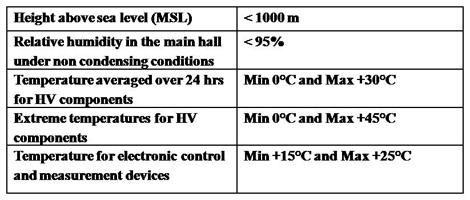
14) What are the ambient conditions for Impulse current test elements?
15) Draw a block diagram of a typical Impulse current generation circuit?
 |
| Source: Haefely- High Voltage Test Techniques -Impulse current Test systems - Type SSGA - 30-200 kA, available online on http://www.haefely.com/ |