In a half wave rectifier, the rectifier unit which primarily consists of a set of diode (uni directional conducting devices), the conduction takes place during positive half cycle of the sinusoidal wave form only and it charges a capacitor which stores the energy. The circuit diagram is shown in Figure-1:
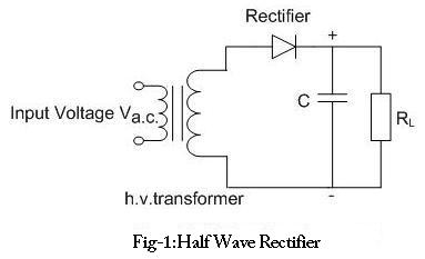
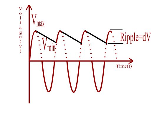
In a half wave rectifier, the rectifier unit which primarily consists of a set of diode (uni directional conducting devices), the conduction takes place during positive half cycle of the sinusoidal wave form only and it charges a capacitor which stores the energy. The capacitor too must be rated for the necessary High Voltage and the Peak Inverse Voltage of the rectifier unit must be 2Vmax where Vmax is the maximum voltage of the input AC wave. If the capacitor is connected to a load, then it slowly loses charge and gets replenished only in the next positive half cycle. The output DC voltage thus does not remain constant but fluctuates between a maximum value and a minimum value. The difference between the maximum and minimum value of the voltage is termed as ripple. Larger the value of the capacitor, lesser would be ripple. In addition the ripple voltage also depends on the frequency of the input AC voltage.
In this experiment, the HV DC rectified output from half wave rectifier is used to perform breakdown studies on symmetric sphere gaps.