
The design efficacy of the insulation system is
ascertained through the one minute Power Frequency Withstand test.
The withstand test voltages are higher than the rated voltages.
Typically, a dry type transformer of 8.7 kV class must withstand
19 kV for one minute at power frequency. IEC 60060 standard specifies
the definitions and requirements for High Voltage Testing of various equipments.
High Voltage Testing Transformers are used as the test
source to generate these high voltages in the laboratory.
A single unit of High Voltage testing transformer can generate
at best up to a voltage of 350 kV. Beyond this rating the
transformer tends to become bulky and unwieldy.
One of the most commonly used methods of obtaining
a High AC Voltage is by combining two or more units
of HV testing transformers in Cascade.
High Voltage testing transformers are essentially
low in power rating and are not used continuously.
The voltage ratings are high and the current ratings are low ,
not in excess of 1 A. The output voltage (especially for
Capacitance & loss factor measurement) must be truly
sinusoidal with a good form factor.
Cascade connection of one or more units of High Voltage
Testing Transformers is one of the most common ways of
generating High Voltages at power frequency in the laboratory.

Generation of high voltages at power frequency is essential
for testing the efficacy of insulation of High Voltage Apparatus used in Power Systems.
The generation and testing is carried out in a laboratory, using High Voltage testing
transformers. These testing transformers can either be located indoor or outdoor.
Testing transformers are different from power transformers in a sense that they are not
rated for high power handling. They are designed to withstand frequent short circuits
when the test object fails or experiences flashover. Therefore, special methods are used,
which are not applicable when generating high voltage in high power applications.
The optimum rating of a single testing transformer unit is 300 kV. Beyond this level,
the cost of insulation rises rapidly and transportation becomes difficult. Cost of
insulation for a single unit is proportional to square of operating voltage. At higher
test voltages a cascade arrangement of several single unit transformers is used to
generate high voltages for testing. Each of the units are enclosed by large size metal
rings to prevent corona.
Cascade Arrangements of Transformers
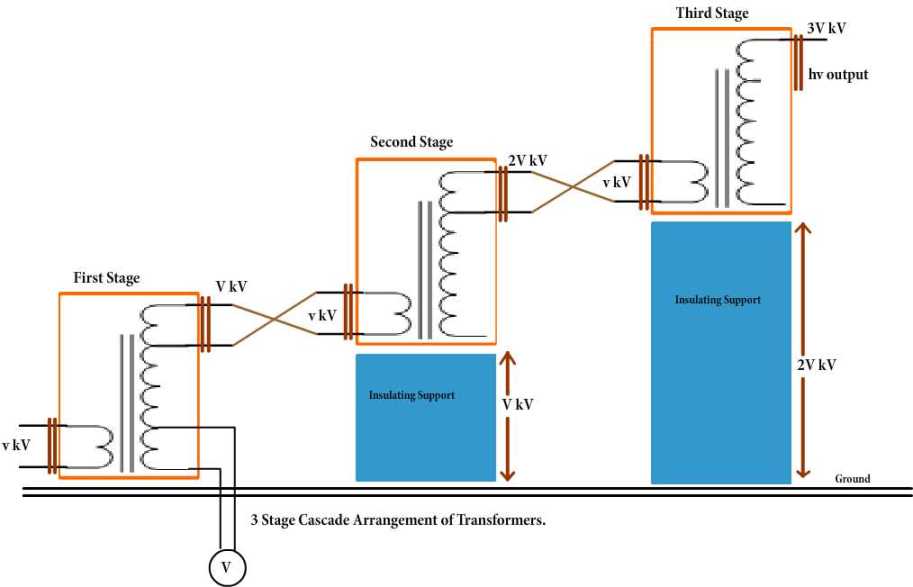
Fig:1: High Voltage Cascade Transformer
The above figure shows a typical cascade arrangement of transformers used to
obtain up to 300 kV from three units each rated at 100 kV. The low voltage
winding is connected to the primary of the first transformer, and this is
connected to the transformer tank which is earthed. One end of the high voltage
winding is also earthed through the tank. The high voltage end and a tapping near
this end is taken out at the top of the transformer through a bushing, and excites
the primary of the second transformer. One end of this winding is connected to the
tank of the second transformer to maintain the tank at high voltage. The secondary
of this transformer too has one end connected to the tank and at the other end the
next stage transformer is fed. This cascade arrangement can be continued further,
if a still higher voltage is required but not more than four stages.
In the cascade arrangement shown, each transformer needs only to be insulated
for 100 kV, and hence the Transformer can be relatively small. If a 300 kV
transformer had to be used instead, the size would be massive. High voltage
transformers for testing purposes are designed purposely to have a poor regulation.
This is to ensure that when the secondary of the transformer is short circuited
(as commonly it happens in flash-over tests of insulation), the current does not
increase to too high a value and to reduce the cost. The impedance of the
transformer should be generally less than 5% and must be capable of giving
the short circuit current for one minute or more depending on the design in practice,
an additional series resistance (commonly a water resistance) is also used in such
cases to limit the current and prevent possible damage to the transformer.
What is shown in the cascade transformer arrangement is the basic principle involved.
The actual arrangement could be different for practical reasons. The number of stages
in this type of arrangement are usually two to four, but very often, three stages are
adapted to facilitate a three-phase operation so that can be obtained between the lines.
In addition to the normal windings, namely, the low voltage winding, high voltage
winding and a third winding known as meter windings is provided to measure the output
voltage. Supply to the units can be obtained from a motor-generator set or through an
induction regulator for variation of the output voltage. The rating of the primary or
the low voltage windings is usually 230 or 400 V for small units up to 100 kVA. For
larger outputs the rating of the low voltage winding may be 3.3 kV, 6.6kV or 11 kV.
Fig.1 shows the cascade transformer units in which the first transformer is at
the ground potential along with its tank. The second transformer is kept on insulators
and maintained at a potential of V2, the output voltage of the first unit above the
ground. The high voltage winding of the first unit is connected to the tank of the
second unit. The low voltage winding of this unit is supplied from the excitation
winding of the first transformer, which is in series with the high voltage winding
of the first transformer at its high voltage end. The rating of the excitation windings
is almost identical to that of the primary or the low or the low voltage winding.
The high voltage connection from the first transformer winding and the excitation
winding terminal are taken through a bushing to the second transformer. In a similar manner,
the third transformer is kept on insulators above the ground at a potential of 2V2 and
is supplied likewise from the second transformer.
Typical Short circuit current for the High Voltage test is around 0.1 A
for dry tests on solid and liquid insulation. About 1 A may be necessary
for wet test on large specimens.
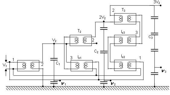
Fig:2: Cascade Transformer unit with isolating transformer for excitation
Where T1,T2,T3- Cascade Transformer Units
lS1,lS2,lS3-Isolation Transformer units
C1,C2,C3-Capacitance Voltage dividers for h.v. measurement after first second and third stages
In Fig.2, a second scheme for providing the excitation
to the second and the third stages is shown. Isolating transformers lS1,lS2,lS3 are 1:1
ratio transformers and are meant for supplying the excitation for the second and the
third stages at their tank potentials. Power supply to the isolating transformers is
also fed from the same a.c. input. This scheme is expensive and requires more space.
The advantage of this scheme is that the natural cooling is sufficient and the
transformers are light and compact. Transportation and assembly is easy. Also the
construction is identical for isolating transformers and the high voltage cascade
units. Three phase connection in delta or star is possible for the three units.
Testing transformers of ratings up to 10 MVA are cascade connected to give high
voltages up to 2.25 MV are available for both indoor and outdoor applications.
In order to reduce the size and cost of the insulation, sometimes transformers
with a center tap on high voltage windings earthed or connected to the tank are
used. This connection results in a cheaper construction, and the high voltage
insulation now needs to be designed for V2/2 , that of second transformer at 5V2/2 ,
and that of the third transformer at 5V2/2.
All the cascade transformer units which are meant for the supply of excitation to
the next stage have large leakage between the primary (or the low voltage winding)
and the excitation windings. Hence, they are invariably provided with compensating windings.

- To understand the generation of high voltage AC for testing purposes through the use of Cascade transformers.
- To use the High Voltage Power Frequency Test Transformer and hence demonstrate the use of Cascade connection to perform breakdown studies on Sphere Gap under varying atmospheric conditions.
- How High AC Voltages are generated for testing ?


- When the page is loaded choose the Diameter of the Sphere value from the displayed dropdown box.
- The sphere gap distance values are populated for selected diameter value and one value should be choosen from the dropdown.
- The user gets displayed the value of Break-down voltage from the database for selected sphere gap distance & diameter of the sphere values.
- The R.M.S Voltage calculated as Break-down voltage/√2 also gets displayed.
- The Room-Temperature and Atmospheric Pressure values in the corresponding text boxes has to be mentioned in order to run the experiment.
- The setup Experiment button is clicked to display the experimental setup of power frequency AC Test Source.
- The number of transformers displayed(1/2/3/4) in the experimental setup is decided by the entered values of diameter of sphere,sphere gap distance,Room temperature and atmospheric pressure.
- The Trigger setup button in clicked to know the voltage value at which break-down occurs.
- The voltage so applied is displayed in the text box.

The main application fields of Power Frequency AC Test Source are:
- High Voltage Testing Transformers are a vital component of a High Voltage Laboratory. The are used to perform the one minute Power Frequency withstand test (also called as Hi-pot testing) for High Voltage power apparatus like Power transformers, motors, generators , switchgear and overhead insulators (both under dry and wet conditions). In many cases, to get the required voltage the transformers must be connected in Cascade.
- High Voltage Testing transformers are also used as a source for measurement of Capacitance, tanδ and partial discharges in High Voltage power equipment. In most of the cases a single high voltage testing transformer is used.
- High Voltage Power Frequency Testing transformers are extensively used in breakdown studies of various solid, liquid, gaseous insulating materials with different electrode combinations.
- They also serve as a source for DC Charging set of the Impulse Voltage Generator and in generating high DC voltages.