PARAMETRIC ANALYSIS OF IMPULSE CURRENT GENERATOR WAVEFORM
CONTROLLER
CHARGING VOLTAGE
Vo in kV:
CAPACITOR VALUES
Cg in µF:
RESISTOR VALUES
Rf in Ω :
R1 in Ω :
INDUCTOR VALUES
Lf in µH:
L1 in µ H:
SIMULATOR
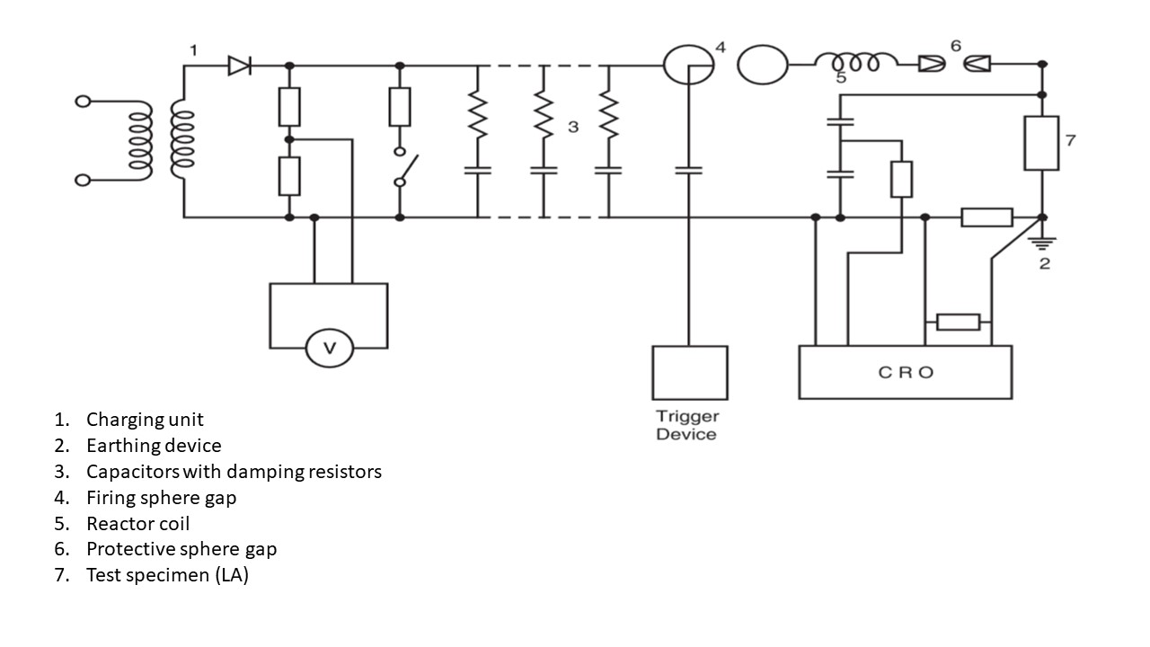
EQUIVALENT CIRCUIT DIAGRAM

INSTRUCTIONS
- The objective of this experiment is to observe the variation in output waveform by varying one parameter and keeping all the others constant.
- When the page loads the user is presented with three input parameter buttons namely Generator Capacitance(Cg),Front Resistance(Rf),Front Inductance(Lf) on left frame and a circuit representation of Impulse current generator on right frame.
- One of the parameter buttons is clicked to continue the experiment for parametric analysis.
- The user gets a display of non-editable parameters namely Charging voltage(VO), Tail resistance(Rt),Load Inductance(Lt) with default values and two editable parameters namely parameter button chosen(Cg,Rf,Lf) with default values.
- The editable parameters are changed by adjusting slider position.
- Then click on open ground switch to give supply to ICG and you can see it in simulator
- The Charge Capacitor button is to be clicked to charge generator capacitors.Charging time of capacitor is displayed by bar on left corner of simulator
- The Trigger generator button is to be clicked to display the mechanism of ICG and the fact that Breakdown has occurred or not is displayed.
- After complete the process the respective graph will be shown. View the waveform carefully how waveform is changing with variation in parameters. And also different wave forms are generated for withstand and flashover.
- Mouse-hover on wave to see the variation of generated voltage with time. You can drag it or Zoom In/Zoom Out the wave form for detail study.
- Find out Front time and tail time from the wave from for each waveform and compare them (how to find out front time and tail time you have to see theory part).
- after finding front time and tail time you can compare the generated Impulse wave with standard switching impulse wave.
CHARACTERISTICS
Copyright © 2011 Indian Institute of Technology Kharagpur,
Licensing Terms