Rectifiers:
Almost all electronic circuits require a dc source of
power. For portable low power systems batteries may be used.
More frequently, however, electronic equipment is energized by
a power supply, a piece of equipment which converts the alter-
nating waveform from the power lines into an essentially direct
voltage.
A device, such as the semiconductor diode, which is
capable of converting a sinusoidal input waveform (whose average value is zero) into a unidirectional (though not constant) waveform, with a nonzero average component, is called a rectifier.
Objective
To study the characteristics of fullwave rectifier with and without filter and to calculate the following parameters.
Ripple factor
Rectification efficiency
Theory
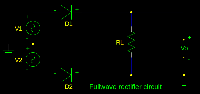
The basic circuit for half-wave rectification is shown below.
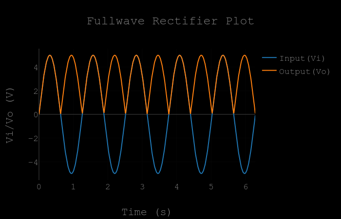
In a rectifier circuit the input is a sinusiodal wave
\( v_i = V_m sin(wt) \)
has a peak value \( V_m \) which is very large compared with the cutin
voltage \( V_T \) of the diode, we assume that \( V_\gamma = 0 \), (The condition \( V_I \neq 0 \) is treated. With the diode idealized to be a resistance \( R_f \) in the ON state and an open circuit in the OFF state.
In the rectifier circuit for positive half cycle of input signal D1 is ON and D2 is OFF. For negative half cycle of input signal D1 is OFF and D2 is ON.
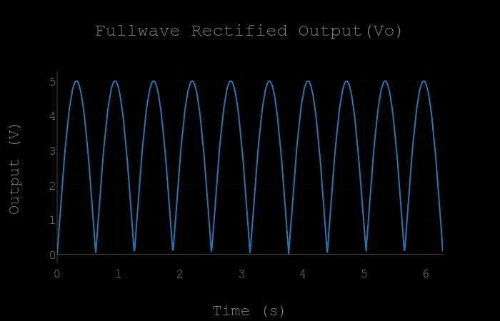
The output voltage \( v_o \) is given as