
Objecitve:
This experiment explains how On-chip timer of 8051 is used to trigger the ADC
Tools Required:
Hardware:
MCU (AT89C51)
ADC0809
Software:
Proteus
Keil Microvision

Knowledge on ADC (Analog to Digital Convertor) 0809
The ADC0809 data acquisition component is a monolithic CMOS device with an 8-bit analog-to-digital converter, 8-channel multiplexer and microprocessor compatible control logic.
Knowledge on 8051 MCU
A microcontroller is a single chip that contains the processor (the CPU), non-volatile memory for the program (ROM or flash), volatile memory for input and output (RAM), a clock and an I/O control unit. The Intel 8051 is an 8-bit microcontroller.
Knowledge of On-Timer of 8051 MCU
8051 MCU has two timers ( Timer 0 and Timer 1). The timers are same as other registers. Each timer is of 16-bit but 8051 has an 8-bit architecture so each timer is accessed as two separate registers of low byte(TL) and high byte(TH).
Knowledge on Proteus software
Proteus 7.0 is a Virtual System Modelling (VSM) which combines circuit simulation, animated components and microprocessor models to co-simulate the complete microcontroller based designs. To know how to design and simulate your circuit in proteus kindly follow the Videos tab.
Knowledge on Keil Microvsion
The µVision IDE from Keil combines project management, make facilities, source code editing, program debugging and complete simulation in one powerful environment.

For more details on 8051 MCU click here
ON-TIMER CHIP OF 8051
The 8051 MCU has two timers ( Timer 0 and Timer 1). Here each timer is of 16-bit. We know that 8051's architecture is of 8-bit so the timers are accessed as two separate registers of low byte(TL) and high byte(TH). The below figure explains the concept,
FUNCTIONS OF TIMER
-
Keeping time and/or calculating the amount of time between events,
-
Counting the events themselves, or
-
Generating baud rates for the serial port.
2. TCON ( Timer Control)
TMOD (Timer Mode)
- It is a 8-bit register
- This is divided as lower 4- bit (Timer 0) and as upper 4-bit (Timer 1)
- The below figure explains the division
TCON (Timer Control)
- It is also an 8-bit register.
- The below figure explains it.
- TCON register is a bit-addressable register.
FORMULA FOR FREQUENCY CALCULATION
TRIGGERING OF ADC USING ON-CHIP TIMER
Triggering of ADC is done by considering the On-Chip Timer as
2. Timer in Mode 2
CHARACTERISTICS AND OPERATION OF MODE 1
- This is done by SETB TR0 for timer 0 and SETB TR1 for timer 1
- It counts up until it reaches its limit of FFFFH
- When it rolls over from FFFFH to 0000, it sets high a flag bit called TF (timer flag)
- When this timer flag is raised, one option would be to stop the timer with the instructions CLR TR0 or CLR TR1, for timer 0 and timer 1, respectively
- TH and TL must be reloaded with the original value and
- TF must be reloaded to 0

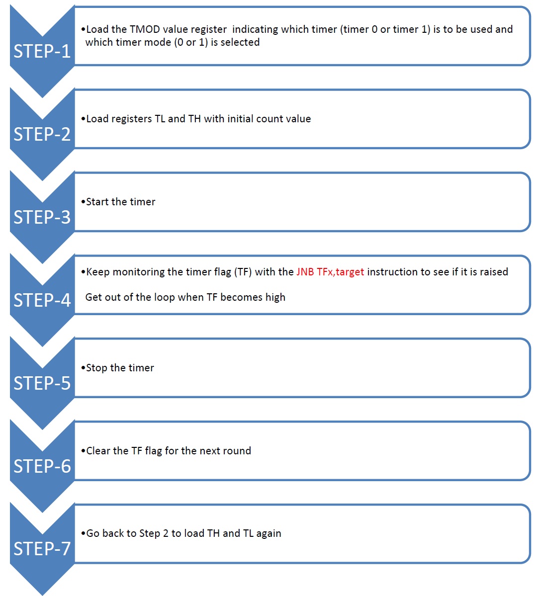
STEP-BY-STEP PROCDURE FOR PERFORMING THE EXPERIMENT
Step-1
|| Components Required ||
- MCU (AT89C51)
- ADC0809
- Signal Generator
- Oscilloscope
- Power Supply
Step-2
||INTERFACING ADC0809-MCU (AT89C51)||
BLOCK DIAGRAM OF ADC-8051 INTERFACING
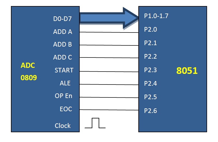
ALGORITHM FOR ADC-8051 INTERFACING
.jpg)
Step-3
ADC & 8051 INTERFACING CODE

PROTEUS ISIS:
The "Proteus ISIS" is required to design and simulate the circuit.
To download the TRIAL VERSION OF PROTEUS Click here.
Proteus Simulation Circuit :
.jpg)
CODE
Code for generating 600KHz frequency on pin2.3:
Let XTAL frequency be 11.0952MHz
Timer's clock frequency = (1/12) X 11.0952 MHz = 1.085 uS.
Required frequency = 600 KHz. ( ADC0809 clock frequecy is 600KHz )
CALCULATION
1) T = 1/f = 1/600 KHz = 2us
2) 1/2 of it(T) for the high and low portion of the pulse is 1us.
3) 1 uS / 1.085 uS = 0.921659 ~ 1
and 65536 -1 =65535 ( in hexadecimal FFFFH)
ASSEMBLY PROGRAM
CLR P2.3 ; clear P2.3
MOV TMOD, #01 ; Timer 0, mode 1( 16-bit mode)
HERE: MOV TL0, # FFH ; TL0 = FFH,low byte
MOV TH0,#0FFH ; TH0 =FFH, high byte
SETB P2.3 ; SET high P2.3
SETB TR0 ; Start Timer 0
AGAIN: JNB TRO,AGAIN ; monitor Timer 0 flag
CLR TR0 ; stop Timer 0
CLR TF0 ; clear Timer 0 flag for next round
CLR P2.3 ; clear P2.3

- Trigger a 10-bit ADC through its on chip timer.
- Use an external 555 timer to trigger a 8-bit ADC.

1. http://www.mikroe.com/eng/chapters/view/64/chapter-1-introduction-to-microcontrollers/
2. The 8051 Microcntroller and embedded systems using assembly and C by Mazidi and Mazidi.
3. http://en.wikibooks.org/wiki/Embedded_Systems/8051_Microcontroller