
The digital-to-analog converter (DAC) is a device widely used to convert digital pulses to analog signals. There are two methods to create a DAC: binary weighted and R/2R ladder. Our target is to interface DAC with 8051 microcontroller and generate a ramp signal by programming the microcontroller.
Tools Required:
Hardware:
MCU (AT89C51)
DAC0808
Counter (IC 79LS43)
Resistors (10k, 8.2k)
Capacitors(33pF, 10uF)
Op-amp
Signal Generator
Oscilloscope
Power Supply
Software:
Proteus
Keil Microvision

Interface DAC with 8051 microcontroller and generate a ramp signal by programming the microcontroller.

DAC (Digital to Analog Converter):
The digital-to-analog converter (DAC) is a device widely used to convert digital pulses to analog signals. There are two methods to create a DAC: binary weighted and R/2R ladder. Most of the integrated circuit DACs, including the MCl408 (DAC0808) used in this section, use the R/2R method because a much higher degree of precision can be achieved by it. The criterion for judging a DAC is its resolution, which is a function of the number of binary inputs. The common ones are 8, 10, and 12 bits. The number of data bit inputs decides the resolution of the DAC because the number of analog output levels is equal to `2^n`, where n is the number of data bit inputs. Therefore, an 8-input DAC such as the DAC0808 provides 256 discrete voltage (or current) levels of output. Similarly, the 12-bit DAC provides 4096 discrete voltage levels. There are also 16-bit DACs, but they are very expensive.
ln the MCl408 (DAC0808), the digital inputs are converted to current (`I_(out)`), and by connecting a resistor to the `I_(out)` pin, we convert the result to voltage.The total current provided by the `I_(out)` pin is a function of the binary numbers at the D0-D7 inputs of the DAC0808 and the reference current (`I_(ref)`), and is represented as:
where `D_0` is the LSB, `D_7` is the MSB for the inputs, and `I_(ref)` is the input current that must be applied to pin 14. The `I_(ref)` current is generally set to 2.0 mA. The generation of current reference (setting `I_(ref)` = 2 mA) is done by using the standard 5V power supply. Now assuming that `I_(ref)` = 2 mA, if all the inputs to the DAC are high, the maximum output current is 1.99 mA (verify it).
Converting `I_(out)` to voltage in DAC0808
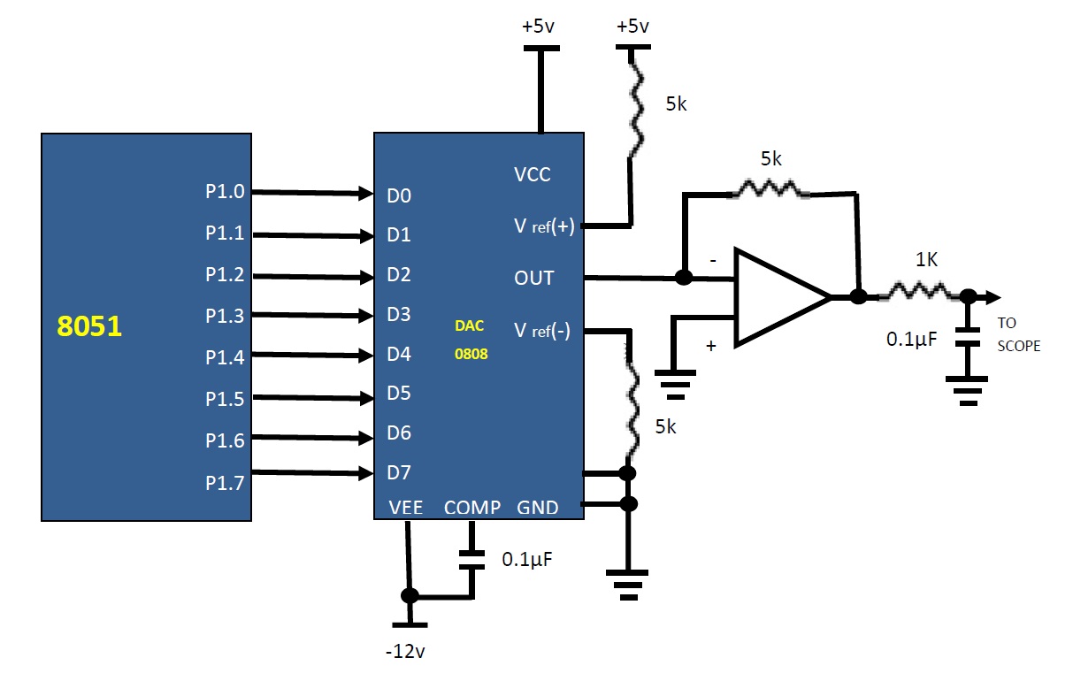
Ideally we connect the output pin lout to a resistor to convert the current to voltage, and monitor the output on the scope. In real life, however, this can cause inaccuracy because the input resistance of the load will also affect the output voltage. For this reason, the `I_(ref)` current output is isolated by connecting it to an op-amp such as the 741 with the the feedback resistor Rf = 5 kilo-ohms . Assuming that R = 5 kilo-ohms, the output voltage changes with the change in the binary input.
Pin Diagram of DAC0808


STEP-1
COMPONENTS REQUIRED
- MCU (AT89C51)
- DAC0808
- Counter (IC 79LS43)
- Resistors (10k, 8.2k)
- Capacitors(33pF, 10uF)
- Op-amp
- Signal Generator
- Oscilloscope
- Power Supply
STEP-2
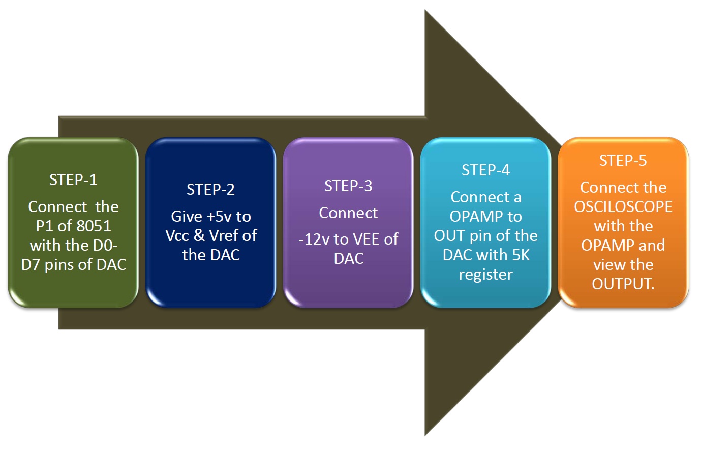
PROCEDURE FOR INTERFACING MCU - DAC0808
BLOCK DIAGRAM:
ALGORITHM FOR INTERFACING 8051 WITH DAC:
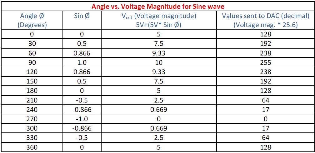
Procedure to generate Sine wave:
To generate a sine wave, first a table is designed whose values represent the amplitude of the sine of the angles between 0 and 360 degrees. The value of the sine function varies from -1.0 to +1.0. Therefore the table values are integer numbers representing the voltage magnitudes for the sine of theta. This method ensures that only integer numbers are output to the DAC by the MCU. To generate the sine wave, the output of DAC is assumed to be 10V. Full scale output of the DAC is achieved when all the data inputs of the DAC are high. Therefore to achieve the full-scale 10V output, we use following equation.
`V_(out) = 5V + 5* sin(phi)`
`V_(out)` of DAC for various angles is calculated.

PROTEUS ISIS:
The "Proteus ISIS" is required to design and simulate the circuit.
Proteus Simulation Circuit:
.jpg)
Pseudocode for sine wave generation:
# include <reg51.h>
sfr DACDATA = P1;
void main ()
{ unsigned char WAVEVALUE [12] = {128,192,238,255,238,192,128,64,17,0,17,64} ;
unsigned char x;
while (1)
{ for (x=0; x<12; x++)
{
DACDATA = WAVEVALUE [x];
}
}
}
Pseudocode for ramp wave generation:
# include <reg51.h>
int main (void)
{
unsigned char i = 0; //Define a counter
P2 = 0xFF; //make port P2 as output port
while (1) // Do forever
{
P2 = i; // copy i into port P2 to be converted
i++; // increment the counter
}
return 0;
}

- Convert the Coefficients generated in Expt-1 into fixed point format.
- Write a C code to design a filter using the coefficients of high pass filter generated in Expt-1.

- Fixed point FIR
- Fixed point FIR filters: theory
- Digital Design of Signal Processing Systems: A Practical Approach By Shoab Ahmed Khan
- Computational Intelligence and Bioinspired Systems: 8th International Work ... edited by Joan Cabestany, Alberto Prieto, Francisco Sandoval