
Objective:
This experiment deals with regulating temperature of a closed chamber by controlling the fan and heater using ATMEGA16 micro controller.
Tools Required:
Hardware:
Software
Proteus
AVR Studio

KNOWLEDGE REQUIRED TO PERFORM THE EXPERIMENT
KNOWLEDGE OF ATMEGA16
KNOWLEDGE OF DC MOTOR (FAN)
A simple DC motor has a coil of wire that can rotate in a magnetic field. The current in the coil is supplied via two brushes that make moving contact with a split ring. The coil lies in a steady magnetic field. The forces exerted on the current-carrying wires create a torque on the coil.
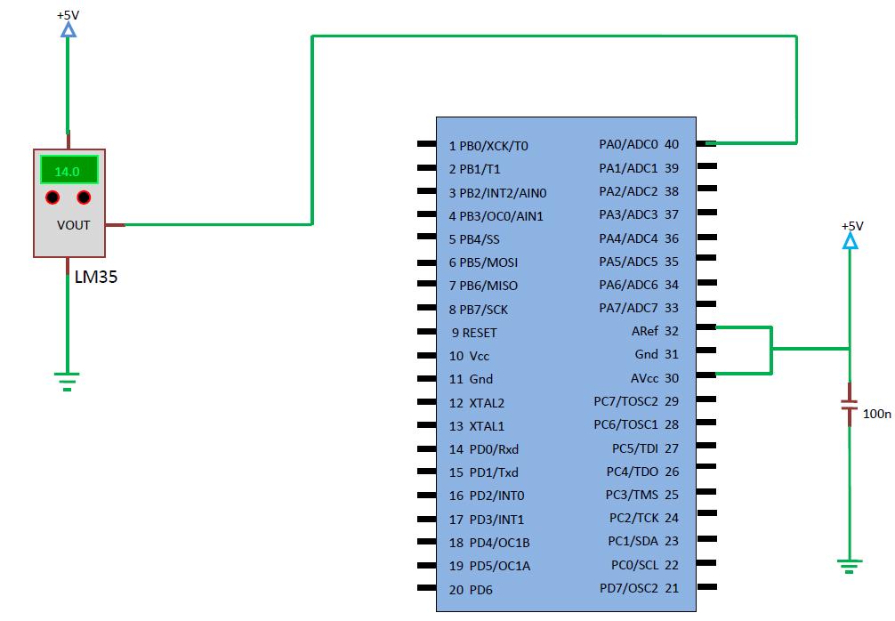
KNOWLEDGE OF LM35 (TEMPERATURE SENSOR)
In this experiment it is required to measure room/chamber temperature in our prototype, so we chose the LM35 IC temperature sensor which can measure temperature from -55 to 150 degree celsius.
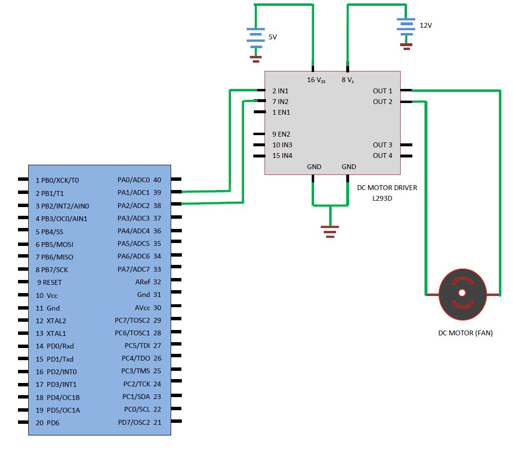
KNOWLEDGE OF L293D (MOTOR DRIVER)
The L293D is designed to provide bidirectional drive currents of up to 1A at voltages from 4.5 V to 36 V. The L293D is designed to provide bidirectional drive currents of up to 600-mA at voltages from 4.5 V to 36 V.
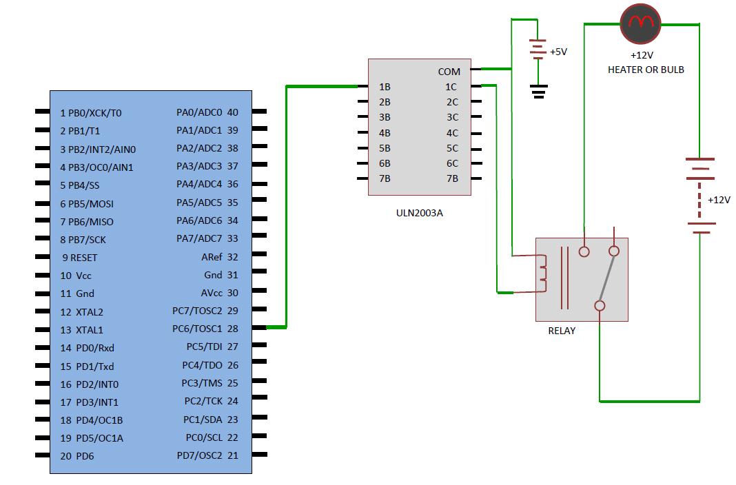
KNOWLEDGE OF RELAY DRIVER (ULN2003A)
The ULN2003A is a high-voltage, high-current darlington transistor arrays.
EXPERIENCE ON AVR STUDIO SOFTWARE
AVR Studio ( 4, 5) is a professional Integrated Development Environment (IDE) for writing and debugging AVR application in Windows 9x / NT / 2000 / XP environments. AVR Studio is an open source software. To know how to program AVR studio kindly follow the Videos tab.
EXPERIENCE ON PROTEUS SOFTWARE
PROTEUS software is designed by LABCENTER ELECTRONICS. The PROTEUS software is used to draw schematic of the circuit and to do the simulation of the circuit . To know how to design and simulate your circuit in proteus kindly follow the Videos tab.

TEMPERATURE CONTROLLER
INTRODUCTION TO TEMPERATURE CONTROLLERS
Temperature controllers are devices used to accurately control process temperature without extensive operator involvement. It is a control system which accepts data from temperature sensors such as thermocouples or Resistance Temperature Detectors (RTD) and compares the actual temperature to the desired set-point temperature, to operate temperature controlling elements like coolers or heaters.
WHY DO WE NEED TEMPERATURE CONTROLLER ?
- The temperature of food items can be controlled to minimize the bacterial growth without affecting its nutrition value.
- For boilers, temperature is important for water and air preheat, fuel oil viscosity, and steam superheat control.
- The temperature control in cold stores reduces the contamination and degradation rate in pharmaceutical, biochemical, beverage and food industries.
- The temperature control in plant growth chambers is important for studying the effect of hybridization, genetic engineering and plant growth regulators.
EXPLANATION
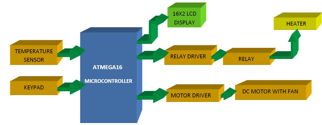
An ATmega16 AVR Microcontroller is used for carrying out all the required computations and control. It has an in-built Analog to Digital converter. Hence an external ADC is not required for converting the analog temperature input into digital value. In the following discussion we will briefly discuss about the temperature sensor used, the microcontroller and the project in general. An inexpensive temperature sensor LM35 is used for sensing the ambient temperature. The system will get the temperature from the sensor IC and will display the temperature on the LCD. This temperature is compared with the set point temperature declared by the user (also displayed on the LCD) using a keypad. We are implementing On/Off control for controlling the temperature. The temperature must be within a certain range otherwise continuous On/Off of the controlling elements (heater and fan) will cause damage to them. We consider the temperature range to be ±2oC compared to the set temparature. If the Room /Chamber temperature goes beyond the upper limit then fan will be switched ON and if temperature goes below the lower limit then heater will be switched ON. At set point both the heater and the fan will be Off.
KNOWLEDGE ON ATMEGA16
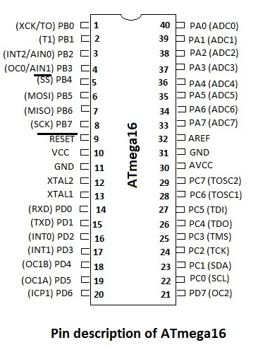
FEATURES OF ATMEGA 16
- 16 kilo bytes of Flash memory.
- 512 bytes of EEPROM.
- 1 kilo bytes of SRAM.
- 131 instructions set.
- 32 x 8 bit general purpose working registers.
- On chip 2 cycle multiplier.
- Programming locks for software security.
- Two 8-bit timers.
- One 16 bit timer.
- 8 channel 10-bit ADC.
- On chip Analog comparator.
- Internal calibrated RC Oscillator.
- 32 programmable I/O lines.
- Programmable serial USART.
- Max Speed : 16 MHz(ATmega16).
- Watchdog timer.
- USB controller support.
- Ethernet controller support.
- LCD controller support.
- DMA controller.
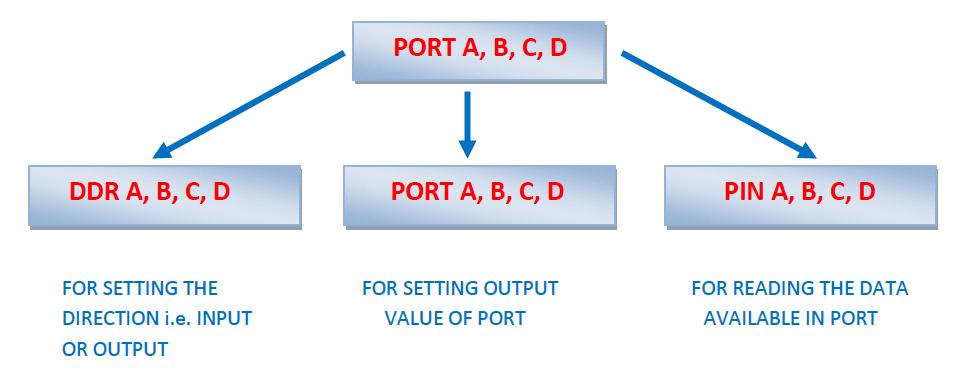
- DDRx
- PORTx
- PINx ; Where x stands for A, B, C, D
BASIC KNOWLEDGE OF AVR STUDIO SOFTWARE
Atmel AVR Studio is an Integrated Development Environment (IDE) for developing and
debugging embedded Atmel AVR applications. It enables full control execution of programs
on the AT90S In-Circuit Emulator or on the built-in AVR Instruction Set Simulator. It provides
a project management tool, source file editor, simulator, assembler and front-end compiler
for C/C++ programming, emulator and on-chip debugger. The AVR Studio gives a seamless and
easy-to-use environment to write, build, and debug C/C++ and assembly codes.
AVR Studio supports source level execution of Assembly programs assembled with the
Atmel Corporation's AVR Assembler and C programs compiled with compilers such as IAR
Embedded Workbench, Code Vision AVR C compiler, GCC(GNU), etc. In AVR studio 5 there
is an integrated C compiler so no need to install separately.
The
Assembler translates assembly source code into object code. The generated object code
can be used as input to a simulator such as the ATMEL AVR Simulator or an emulator
such as the ATMEL AVR In-Circuit Emulator. The Assembler also generates a PROMable
hex code which can be programmed directly into the program memory of an AVR microcontroller.
The Assembler generates fixed code allocations, consequently no linking is necessary.
AVR Studio 4(or higher version) has a modular architecture which allows even more interaction with 3rd party software vendors. GUI plug-ins and other modules can be written and hooked to the system.
For more knowledge on AVR Studio click here
BASIC KNOWLEDGE OF PROTEUS SOFTWARE
PROTEUS software is designed by LABCENTER ELECTRONICS. The PROTEUS software is mainly used to draw schematic of the circuit and to do the simulation of the circuit. It contains all types of components required for the schematic of the circuit. PCB can be designed in this circuit. In ISIS ( part of PROTEUS) it is used for simulation of the circuit and to draw schematic of the circuit.In ARES ( part of PROTEUS) it is used for PCB designing.
For more knowledge on PROTEUS SOFTWARE click here
CONCLUSION

REQUIREMENTS:-
- ATMEGA16 microcontroller
- Temperature sensor (LM35)
- 16 X 2 LCD
- 4X4 Keypad
- Heater (AC Bulb)
- Fan
- Relay and relay driver
- DC motor and motor driver
SOFTWARE :
- PROTEUS software (for simulation of the circuit)
- AVR Studio5 (for programming and compiling)
BLOCK DIAGRAM
STEP-1:
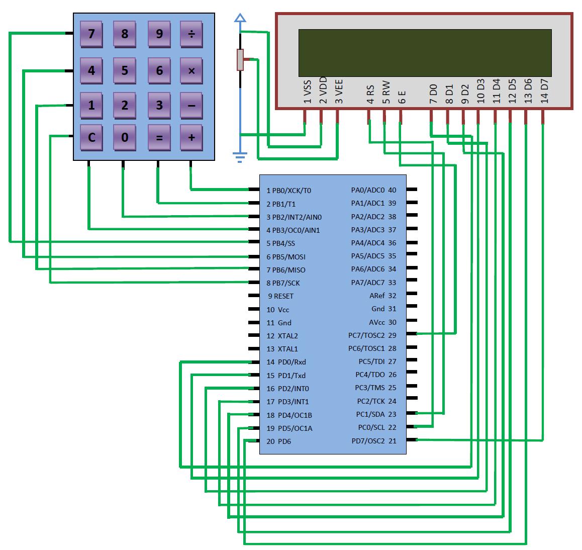
ALGORITHM TO INTERFACE LCD 16x2 WITH THE MICROCONTROLLER
- Initialize the LCD.
- Select the command or instruction register (RS=0 or RS=1).
- Set RW low (to write to LCD)
- Send a high to low pulse on the EN pin.
- Check if the LCD is busy (Optional step, it eliminates the delay use)
- Move to instruction or command function.
- Repeat above steps.
- Select a port of ATMEGA16 microcontroller and declare it as I/O port.
- Port PB0-PB3 are used to read the row results and Port PB4 - PB7 are used to read the column results.
- High nibble for output (columns) and low for input (rows).
- Pull-up-resistors to lower four port pins (PB0-PB3) on these i/ps are enabled.
- One after the other port bits PB6, PB5 and PB4 set low and PB0-PB3 are checked for zero.
- Register pair Z (ZH-ZL) points to table with key codes that are pressed.
- The key code is read from the table in the flash memory to the register R0.
- Use the stored value from the register.
STEP-2 : -
STEP-3 :
STEP-4:
STEP-5 :
Next challenge is that you have to reduce the temperature until it reaches the set temperature for this you have to take some cooling effect so as per cost concern you can choose fan (for experimental purpose) but microcontroller cannot give the required amount of current that is needed by the fan (DC motor) for you have to choose a DC motor driver (rating : - 12V, 1.2A) i.e., L293D. Now write the final code so that the microcontroller can sense the temperature from heater(bulb) by the temperature sensor and reduces the temperature by switching ON the FAN to reach the set point temperature by switching OFF the heater or continue to switch ON the heater (bulb) if the temperature is 2⁰C then the set point temperature.
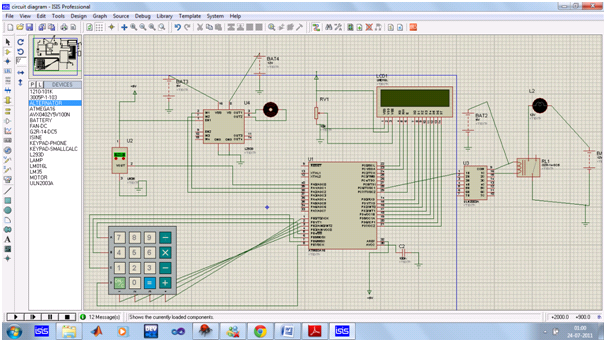
FINAL CIRCUIT DIAGRAM
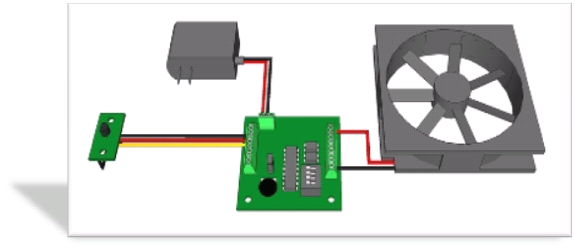
FINAL SET-UP
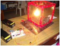
FIG : - In working condition

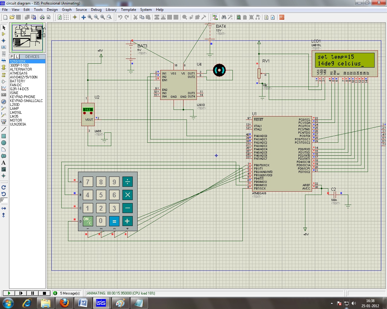
PROTEUS ISIS:
The "Proteus ISIS" is required to design and simulate the circuit. The circuit diagram for Proteus is provided.
Circuit Diagram for Proteus
Code for AVR Studio:
#include<avr/io.h> //standard AVR header
#include<util/delay.h> //delay header
#include<avr/interrupt.h> //interrupt header
#define F_CPU 12000000
#define KEY_PRT PORTB//keyboard PORT
#define KEY_DDR DDRB//keyboard DDR
#define KEY_PIN PINB//keyboard PIN
#define LCD_DPRT PORTD //LCD DATA PORT
#define LCD_DDDR DDRD //LCD DATA DDR
#define LCD_DPIN PIND //LCD DATA PIN
#define LCD_CPRT PORTC// LCD COMMANDS PORT
#define LCD_CDDR DDRC//LCD COMMANDS DDR
#define LCD_CPIN PINC//LCD COMMANDS PIN
#define LCD_RS 0 //LCD RS
#define LCD_RW 1 //LCD RW
#define LCD_EN 7 //LCD EN
void lcdinit(void);
void lcd_gotoxy(unsigned char,unsigned char );
void lcdprint(char*);
void lcdcommand(unsigned char);
void delay_us(unsigned int);
void delay_ms(unsigned int );
void lcddata(unsigned char);
unsigned char keypadcall(void);
unsigned char keypad[4][4]={'A','3','2','1',//keypad declaration as a 4x4 matrix
'B','6','5','4',
'C','9','8','7',
'D','#','0','*'};
void main(void)
{
int ADCH_temp,x,y,a,b,c,d,e,ADC_temp=0,i;
DDRA=0b00000110; //PINA1 and PINA2 are outputs and the
rest of the pins of PORTA are inputs
ADCSRA=0X87; //make ADC enable and select clk/128*
ADMUX=0XE0; //2.56Vref ,single
ended channel ADC0,data will be left justified
sei(); //enable interrupt
lcdinit(); //LCD initialisation function
lcd_gotoxy(1,1); //LCD cursor positioning function
lcdprint("set temp="); //LCD print function
delay_us(1000); //wait
a= keypadcall(); //keypad call for the first digit of temperature
b= keypadcall(); //keypad call for the second digit of temperature
c=atoi(&a); //conversion from character to integer
d=atoi(&b); //conversion from character to integer
e=10*c+d;
//the set temp entered finally converted to integer form
while(1) //stay here forever
{ ADC_temp=0;
for(i=0;i<16;i++) //do the ADC conversion 16 times to improve the accuracy
{
ADCSRA|=(1<<ADSC); //start conversion
while((ADCSRA&(1<<ADIF))==0); //wait for end of conversion,ADIF flag set
ADCH_temp=ADCH; //the variable holds the current
temperature
ADC_temp+=ADCH_temp; //accumulate results(16 samples)
}
ADC_temp=ADC_temp>>4; //average the 16 samples
x=ADC_temp/10+48; //required to convert the temperature(first digit)
to ascii(decimal) value in order to display it on LCD
y=ADC_temp%10+48; //required to convert the temperature(second digit) to
ascii(decimal) value in order to display it on LCD
lcd_gotoxy(1,2);
lcddata(x); //pass the ascii value of first digit in order to display it on the LCD
lcddata(y); //pass the ascii value of second digit in order to display it on the LCD
lcdprint("deg celcius");
delay_us(1000); //wait
if(ADC_temp<=(e-2)) //if current temp is 2 degree celsius less than the set temperature
PORTC=PORTC|0b01000000; //turn on the heater connected to PORTA6
if(ADC_temp==e) //if current temp is equal to the set temperature
{
PORTC=PORTC&0b00000000; //turn off the heater
PORTA=PORTA&0b00000000; //turn off the fan
}
if (ADC_temp>=(e+2)) //if current temp is 2 degree celsius more than the set temperature
PORTA=PORTA|0b00000100; //turn on the fan
}
}
void lcdinit()
{
LCD_DDDR= 0XFF;
LCD_CDDR= 0XFF;
LCD_CPRT &=~(1<<LCD_EN); //LCD_EN=0
delay_us(2000);//wait for init
lcdcommand(0X38); //init LCD 2 line, 5X7 matrix
lcdcommand(0x0E); //display on,cursor on
lcdcommand(0X01); //clear LCD
delay_us(2000);//wait
lcdcommand(0X06); //shift cursor right
}
void lcdcommand(unsigned char cmnd)
{
LCD_DPRT=cmnd; //send cmnd to data port
LCD_CPRT&=~(1<<LCD_RS); //RS=0 for command
LCD_CPRT&=~(1<<LCD_RW); //RW=0 for write
LCD_CPRT|=(1<<LCD_EN); //EN=1 for H-to-L pulse
delay_us(1); //wait to make enable wide
LCD_CPRT&=~(1<<LCD_EN); //EN=0 for H-to-L pulse
delay_us(100); //wait to make enable wide
}
void delay_us(unsigned int d)//delay in micro secs
{
_delay_us(d);
}
void delay_ms(unsigned int d)/*delay in milli secs*/
{
_delay_ms(d);
}
void lcd_gotoxy(unsigned char x,unsigned char y)
{
unsigned char firstcharadr[]={0x80,0xC0,0x94,0xD4};
lcdcommand(firstcharadr[y-1]+x-1);
delay_us(100);
}
void lcdprint(char *str)
{
unsigned char i=0;
while(str[i]!=0)
{
lcddata(str[i]);
i++;
}
}
void lcddata(unsigned char data)
{
LCD_DPRT=data; //send data to data port
LCD_CPRT|=(1<<LCD_RS); //RS=1 for data
LCD_CPRT&=~(1<<LCD_RW); //RW=0 for write
LCD_CPRT|=(1<<LCD_EN); //EN=1 for H-to-L pulse
delay_us(1); //wait to make enable wide
LCD_CPRT&=~(1<<LCD_EN); //EN=0 for H-to-L pulse
delay_us(100); //wait to make enable wide
}
unsigned char keypadcall(void)
{
unsigned char colloc,rowloc;
//keyboard routine.this sends the ASCII code for the pressed key to PORTB
KEY_DDR=0XF0;
KEY_PRT=0XFF;
while(1) //repeat forever
{do
{
KEY_PRT &=0X0F; //ground all rows at once
colloc=(KEY_PIN&0X0F);
//read columns
}while(colloc!=0X0F); //check until all keys released
do
{
do
{ delay_ms(20); //call delay
colloc=(KEY_PIN&0X0F); //see if any key is pressed
} while (colloc==0X0F); //keep checking for key press
delay_ms(20); //call delay for
debounce
colloc=(KEY_PIN&0X0F); //read columns
} while (colloc==0X0F); //wait for key press
while(1)
{KEY_PRT=0XEF;//ground rows
colloc=(KEY_PIN&0X0F); //read all
the columns
if(colloc!=0X0F) //col detected
{
rowloc=0; //save row loc
break; //exit
while loop
}
KEY_PRT=0XDF; //ground row1
colloc=(KEY_PIN&0X0F); //read
the columns
if(colloc!=0X0F) //col detected
{
rowloc=1; //save row loc
break; //exit
while loop
}
KEY_PRT=0XBF; //ground row 2
colloc=(KEY_PIN&0X0F); //read the
columns
if(colloc!=0X0F) //col detected
{
rowloc=2; //save row loc
break; //exit
while loop
}
KEY_PRT=0X7F; //ground row 3
colloc=(KEY_PIN&0X0F); //read the
columns
rowloc=3; //save row loc
break;//exit while loop
}
//check column and send
the result for display on LCD,
// also return the value to main function in order to convert the
character into integer
if (colloc==0X0E)
{lcddata(keypad[rowloc][0]);
return(keypad[rowloc][0]);
}
else if (colloc==0x0D)
{lcddata(keypad[rowloc][1]);
return(keypad[rowloc][1]);
}
else if (colloc==0X0B)
{lcddata(keypad[rowloc][2]);
return(keypad[rowloc][2]);
}
else
{lcddata(keypad[rowloc][3]);
return(keypad[rowloc][3]);
}
break;//exit while loop
}
}

DESIGN PROBLEM:-
- Design a temperature sensor using any other temperature sensor such as thermocouple, thermistors or RTD.

ATMEGA16 KNOWLEDGE
LM35 KNOWLEDGE
L293D KNOWLEDGE
ULN2003A KNOWLEDGE
- AVR STUDIO
- PROTEUS SOFTWARE