
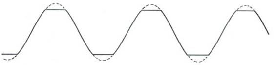
Mechanical looseness shows up in the frequency domain as a large number of harmonics of running speed when lightly loaded. Typically ½ harmonics shows up, as 1½ X, 2½ X, etc. The harmonics show up because of clipping of the waveform when the loose parts hit against their limits of movement. The vibrating part is not allowed to swing to the full extreme of motion that it would like because it hits up against physical stops.
This experiment helps the student to understand the effect of looseness in rotating systems. Experiments can be done by virtually creating and removing mechanical looseness in a machinery. The vibration frequency and amplitudes can be compared to study the effect of looseness.
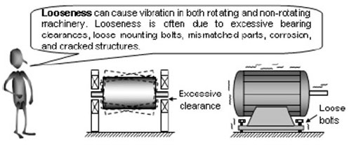
Mechanical looseness, or the improper fit between componet parts, is generally characterized by a long string of rotating frequency harmonics or ½ rotating frequency harmonics at abnormally high amplitudes. These harmonics may be sporadic. For example, looseness may display peaks at 2X, 3X, 4X, 5X, 6X, etc. or at 3X, 3.5X, 4X, 5.5X, 6X, etc.
(a) Causes
Possible causes of wear/looseness are -
(i) The machine has come loose from its mounting.
(ii) A machine component has come loose.
(iii) The bearing has developed a fault which has worn down the bearing elements, or the bearing seat.
Effects
(i) If the looseness is bearing related, the effects are the same as imbalance, only more severe.
(ii) If looseness is generated from a component (for example, a fan blade), there is a possibility the part will become detached, causing secondary damage.

Mechanical Looseness generate vibration in rotating system.
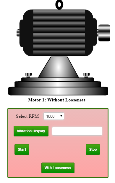
"The objective of this experiment is to identify the presence of loose components in rotating systems using vibration monitoring". The experimental setup has two modules: one for system with loose component and other one without looseness. The student can conduct experiment in both the modules for a selected RPM and compare the vibration spectrum for identifying mechanical looseness. This experiment can be conducted by varying the bearing rotational speed, to study the effect of speed on vibration level and frequency.

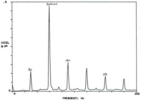
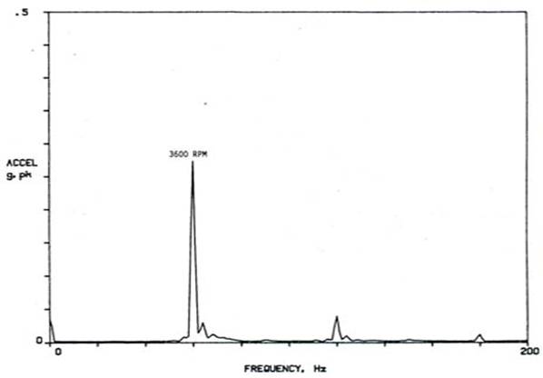
Mechanical looseness shows up in the frequency domain as a large number of harmonics of running Speed when lightly loaded. Typically ½ harmonics shows up, as 1½ X, 2½ X, etc. The harmonics show up because of clipping of the waveform when the loose parts hit against their limits of movement. Figure 1 is an illustration of a sine wave that has been clipped. The vibrating part is not allowed to swing to the full extreme of motion that it would like because it hits up against physical stops. The sine wave of its motion is clipped and the resulting spectrum of looseness is shown in Fig 1.1. This spectrum was created by clamping a 3600-rpm motor with an imbalance in a vise and then loosening the vise hold-down bolts until things rattled. Upon retightening, the 3600-rpm vibration dropped, as did the harmonics. The ½ harmonics disappeared.(Fig 1.2)
In addition to harmonics, looseness can be detected by a decrease in amplitude at higher load. On fans and pumps, higher load causes greater thrust forces which pins the machine against its stops, thus limiting free motion due to looseness.
Some sources report ½ harmonics, and other report 1X harmonics, for looseness. Both are observed in place. It depends on the nature of the loose part and how it interacts with the rotating imbalance. Generally, the presence of ½ harmonics indicates a more severe condition of looseness. On all kinds of machines, looseness can be confirmed by changing the load and observing the vibration.
Over many years, the frequency of vibration due to looseness has been reported as 2X rpm. A macine's base that is rocking on the floor will bounce against the floor much like a chair with uneven legs. Once end "bumps" at one-half of the cycle and the other end at the other half cycle, producing a vibration at twice the rotational speed. However, with the increased use of spectrum analyzers that redily show all the vibrations of the frequency spectrum, looseness has been reported to create ½ X rpm vibration at slightly less than ½ X rpm. Looseness can create vibration at other multiples of rpm such as ½ X, 1½ X, 2X, 2½ X, 3X, 3 ½ X and so on.
For the usual spectrum that is created by mechanical looseness, the above multiples are not always present on the spectrum. Instead, only one or two may be present. For example, a bearing that is loose in its housing may produce a ½ X rpm peak plus one at 1½ X rpm peak. In still another situation, a loose bearing may produce a ½ X rpm peak plus one at 1 ½ X peak is missing, but the 2 ½ X and 3 ½ X peaks are present. In other words, the various peaks that are related to ½ X rpm can be present but are usally sporadic. In situations of extreme looseness, many more of these peaks will be present. These frequencies are only a warning of possible looseness.
There may be many situations when a part is actually loose, and yet the multiples as described do not appear on the spectrum. For looseness to be revealed on a spectrum, vibration at another frequency must be large enough to cause the loose part to move. For example, visualize a small, well-balanced motor placed on a simple table top and run at its service speed. Although the motor is not bolted down, absense of vibration due to unbalance or any other sources is not great enough to cause the loose motor to rattle on the table. Therefore, a vibration spectrum will not show the symptoms of looseness even though the motor is actually loose.
If additional unbalance is added to the motor pulley, the unbalance amplitude of 1X rpm will increase and yet not to be strong enough to rattle the weight of the rotor. Peaks that reveal looseness will still not be present. Step-by-step increases of unbalance will finally reach a point where the rotating unbalance force will cause the loose motor to momentarily lift slightly from the table, causing a rattle. Sometimes only a slight rattle will produce several of the peaks due to looseness. At other times, a much stronger the rattle, stronger the possibility for more peaks.

Procedure for Oil Whirl Monitoring -
The experimental setup has two modules: one for system with loose component and other one without looseness. The student can conduct experiment in both the modules for a selected RPM and compare the vibration spectrum for identifying mechanical looseness. This experiment can be conducted by varying the bearing rotational speed, to study the effect of speed on vibration level and frequency. This can be conducted in following easy steps:-
Step 1: Click on Simulator. You get the experimental setup for running the motor at selected RPM (1000 to 5000) and provision for vibration level as "With Looseness" or "Without Looseness".
Step 2: Select RPM = 1000. (RPM can be selected from the range from 1000 - 5000) as desired by the user.
Step 3: Click the Start button. The motor start running and selected RPM.
Step 4: Click vibration display. The vibration spectrum the acceleration Y axis and frequency on X axis displayed. Now Stop button. Note down the average vibration level and vibration level corresponding to the selected RPM (frequency = RPM/60).
Step 5: Change RPM and then repeat the step 2 to step 4 and note down the vibration levels corresponding to rotational frequency and the average value.
Step 6: Repeat for all RPM. Plot vibration level against RPM and comment on the results you get. Do you observe any trend? Is the trend linear or non-linear?
Step 7: Click the button bent shaft from the control panel. Now the motor is fitted with a shaft which is bent repeat all previous steps and collect the vibration level and different RPM. Plot the vibration level against RPM as done the previous step. Do you observe any trend? Is the trend linear or non-linear?
Step 8: Complete the vibration levels of the motor at different RPMs. When a bent shaft is used and when a shaft is with no bent is used. Do the vibration levels increased when a bent shaft is used for the same RPM? If so, explain the reasons for your comment.


1. In which frequency domain the mechanical looseness appears in vibration analysis?
2. How do you diagnose mechanical looseness?
3. What are the effects of mechanical looseness?
4. What are the corrective measures for looseness?
5. What are the reasons for looseness?
OBJECTIVE QUESTION -
1. what are the peaks appear mechanical looseness?
a. 0.5x
b. 1x
c. 2x
d. 3x and 3.5x
e. All the above
2. what are the possible causes of looseness
a. The machine has come loose from its mounting
b. A machine component has come loose
c. The bearing has developed a fault which has worn down the bearing elements, or the bearing seat.
d. All the above
e. None of the above
3. what is the effect of looseness
a. If the looseness is bearing related, the effects are the same as imbalance, only more severe.
b. If looseness is generated from a component (for example, a fan blade), there is a possibility the part will become detached, causing secondary damage.
c. All of the above
d. None of the above

- ANSI S2.2-1959 (R 1990) American National Standard Methods for the Calibration of Shock and Vibration Pickups.
- ANSI S2.11-1961 (R 1986) American National Standard for the Selection of Calibrations and Tests for Electrical Transducers Used for Measuring Shock and Vibration.
- ANSI S2.10-1971 (R 1990) American National Standard Methods for Analysis and Presentation of Shock and Vibration Data.
- ANSI S2.17-1980 (R 1986) American National Standard-Techniques of Machinery Vibration Measurement.
- ANSI S2.7-1982 (R 1986)(ASA 42) American National Standard-Balancing Terminology.
- ANSI S2.38-1982 (R 1990) American National Standard-Field Balancing Equipment-Description and Evaluation.
- ANSI S2.42-1982 (R 1990) American National Standard-Procedures for Balancing Flesible Rotors.
- ANSI S2.40-1984 (R 1990) American National Standard-Mechanical Vibration of Rotating and reciprocating Machinery-Requirements for Measuring Vibration Severity.
- ANSI S2.43-1984 (R 1990) American National Standard-Criteria for Evaluating Flexible Rotor Balance.
- ANSI S2.41-1985 (R 1990) American National Standard-Mechanical Vibration of Large Rotating Machines With Speed Range from 10 to 200 rev/s-Measurement and Evaluation of Vibration Severity in situ.
- ANSI S2.60-1987 American National Standard-Balancing Machines-Encloseres and Other Safety Measures.
- ANSI S2.19-1989(ASA 86) American National Standard-Mechanical Vibration-balance Quality Requirements of rigid Rotors, Part1: Determination of permissible residual Unbalance.
- ANSI S2.61-1989 American National Standard Guide to the Mechanical Mounting of Accelerometers.
- API 670. American Petroleum Institute. Non-contact Vibration and Axial Position Monitoring System.
- API 678. American Petroleum Institute. Accelerometer Based Vibration Monitoring System.
- API 541. American Petroleum Institute. Maximum Permission Vibration for Form-wound Squirrel-cage Induction Motors.
- Compressed Air & Gas Institute. In Service Vibration Standards for Centrifugal Compressors.
- Bently Nevada Seminar. Machine Protection Seminer, Bently Nevada, Minden, Neveda.
- Michael P. Blake and William S. Mitchell. Vibration and Acoustic Measurement Handbook, Spartan Books, 1972.
- Heinz P. Bloch and Fred K. Geitner. Machinery Failure Analysis and Troubleshooting. Gulf Publishing Company, 1986.
- Simon Braun. MSA-Mechanical Signature Analysis. American Society of Mechanical engineers (ASME), 1983.
- Jens T. Broch, Mechanical Vibration and Shock Measurements, 2d ed., 3rd impression, Bruel & Kjaer, Denmark, April 1984.
- Bruel & Kjaer Seminar. Modern techniques of Machine Vibration Analysis, Bruel & Kjaer, Naerum, Denmark.
- Bruel & Kjaer, Vibration Analysis of Machinery, Bruel & Kjaer, Naerum, Denmark.
- Bruel & Kjaer, Digital Signal Analysis Using Digital Filters and FFT Techniques. Bruel & Kjaer, Naerum, Denmark, January 1985.
- Ralph T. Buscarrello. Practical Solutions to Machinery and Maintenance vibration Problems. Update International, Lakewood, Colo.
- Edgar J. Gunter. Selected Papers on Field Balancing of Rotating machinery-Advanced Theory and Techniques. Vibration Institute, Willowbrook, Ill, May 1983.
- Cyril M. Harris and Charles E. Crede. Shock and Vibration Handbook, 2d ed., McGraw-Hill, New York, 1976.
- Cyril M. Harris. Shock and Vibration Handbook, 3d ed., McGraw-Hill, New York, 1988.
- J.P. Den Hartog. Mechanical Vibrations, 4th ed., McGraw-Hill, New York, 1956.
- J.P. Den Hartog. Mechanical Vibrations, 4th ed., Dover Publications, Mineola N.Y., 1985.
- Hewlett-Packard Application Note 243-1. Effective Machinery Maintenance Using Vibration Analysis. Hewlett-Packard Company, Palo Alto, Calif., 1983.
- Hewlett-Packard Application Note 243. The Fundamental of Signal Analysis. Hewlett-Packard Company, Palo Alto, Calif., 1982.
- Robert S. Jones. Noise and Vibration Control in Buildings. McGraw-Hill, New York, 1984.
- J. M. Juran. Quality Control Handbook, 3rd ed., McGraw-Hill, New York, 1979.
- Mechanical Technology Incorporated (MTI). June 1987 Seminar, Rotating Machinery, Vibration Analysis and Diagnostic Techniques. MTI, Latham, N.Y., 1973.
- John S. Mitchell. An Introduction to Machinery Analysis and Monitoring. PennWell Publishing, Tulsa, Okla., 1981.
- John Piotrowski. Shaft Alignment Handbook. Marcel Dekker, New York, 1986.
- Singiresu S. Rao. Mechanical Vibrations. Addition Wesley, Reading, Mass., 1986.
- J.D. Smith. Gears and Their Vibration: A Basic Approach to Understanding Gear Noise. Marcel Dekker, New York, 1983.
- W. Soedel. Vibration of Shells and Plates. Marcel Dekker, New York, 1981.
- Vibration Institute Seminar Procedings. Balancing of Rotating Machinery-Houseton, Texas. Vibration Institute, Willowbrook, III., February 26-28, 1980.
- Vibration Institute Course. Machinery Vibration Analysis I Course-Tempe, Arizona. Vibration Institute, Willowbrook, III., March 1-4, 1988.
- The Balance Quality of Rigid Rotors, ISO DR 1940.
- AD-A171 031, P.D. McFadden. "Examination of a Technique for the Early Detection of Failure in Gears by Signal Processing of the Time Domain Average of the Meshing Vibration." Commonwealth of Australia, 1986, ARL-AERO-PROP-TM-437.
- AD-A182 572, P.D. McFadden. "Interpolation Techniques for the Time Domain Average of the Meshing Vibration Data with Application to Helicoptor Gearbox Monitoring." Commonwealth of Australia, 1986, ARL-AERO-PROP-TM-437.
- AD-A173 851, P.D. McFadden. "Analysis of the Vibration of the Input Bevel Pinion in Ran Wessex Helicoptor Main Rotor Gearbox WAK 143 Prior to Failure." Commonwealth of Australia, 1985, ARL-AERO-PROP-R-169.
- AD-A155 199, P.D. McFadden. "Proposal for Modifications to the Wessex Helicoptor Main Rotor Gearbox Vibration Monitoring Program." Commonwealth of Australia, 1985, ARL-AERO-PROP-TM-422.
- Hydraulic Institute Application Standards B-74-1, 1967.
- S2.5. American Standard Recommendations for Specifying the Performance of Vibration Machines.
- J. I. Taylor. "Identification of Bearing Defects by Spectral Analysis." ASME Publication 79-DET-14, 1979.
- Harvey L. Balderston. "The Detection of Incipient failure in Bearings." Materials Evaluation, Vol. 27, No. 6, June 1969, pp. 121-128.
- De Jongh, Frits M., and van der Hoeven, Pieter, "Aoolication of a Heat Barrier Sleeve to Prevent Syncronous Rotor Instability," Proceedings of the Twenty-Seventh Turbomachinery Symposium, Texas A & M University, College Station (September 1998).
- American Petroleum Institute, Tutorial on the API Standard Paragrapghs Covering Rotor Dynamics and Balancing: An Introduction to Laterral Critical and Train Torsional Analysis and Rotor Balancing, API publication 684(Washington, D.C.: American Petroleum Institute, 1996).
- Muszynska, A, "One Lateral Mode Isotropic Rotor Reponse to Nonsyncronous Excitation," Proceedings of the Course on the Rotor Dynamics and Vibration in Turbomachinery, von Karman Institute for Fluid Dynamics, Belgium (September 1992).
- Machinary Lubrication 5/2005
- http://www.mechanicalengineeringblog.com/tag/looseness/
- http://www.update-intl.com/VibrationBook13b.htm
- http://www.machinediagnostics.com/PDF/Vibration/VibrationGuide.pdf
- http://http//:www.mech.uq.edu.au/courses/mech7350/lecture-notes-in-pdf/mech7350-17-fault-diagnosis.pdf
- http://www.vtab.se/training/vibration-school/mechanical-looseness/?lang=en
- http://www.vibanalysis.co.uk/vibanalysis/looseness/looseness.html