
Unbalance is the most common rotor system malfunction. Its primary symptom is 1X vibration, which, when excessive, can lead to fatigue of machine components. In extreme cases, it can cause wear in bearings or internal rubs that can damage seals and degrade machine performance.
Static imbalance is a typical problem of rotating machinery leading to severe vibration.
The primary symptorm of unbalance is 1X vibration. Unbalance can produce high rotor and casing vibration, and it can produce vibration in foundation and piping systems. 1X vibration can also contribute to stress cycling in rotors, which can lead to eventual fatigue failure. Unbalance - induced vibration can also cause internal rubs in machinery, especially when passing through resonances.
Diagnosis of unbalance can be complicated by the fact that many different malfunctions can produce 1X vibration. Mechanical and electrical runout, rotor bow, thermal bow, electrical noise, coupling problems, shaft cracks, loose rotating parts, trapped debris or fluids, rub, decreasing foundation spring stiffness, and various electric motor problems can all produce 1X or near 1X vibrations. Because so many malfunctions can masquerade, as unbalance, the machinery diagnostician should be careful to establish unbalance as the root cause before balancing a machine. A loose rotating part can cause an intermittent or continuous change in 1X vibration.
Unbalancing rotary part generates vibration forces resulting in high stresses in the shaft and bearings. Measurement of these forces can give valuable input in accessing the reliability of such systems. This experiment shows the vibration forces generated due to a selector unbalance and RPM. The vibration force due to unbalance vary with respect to the speed of the rotor and the unbalance quantity.

The objective of the experiment is to study the effect of an unbalanced mass at a distance from the axis of rotation of the shaft and rotation speed. Vibration level generated due to static unbalance can be studied for various combinations of the radial distance of the unbalance mass, shaft RPM and the unbalance mass.

Static Balancing Studies of Rotary Systems -
Unbalance is the most common rotor system malfunction. Its primary symptom is 1X vibration, which, when excessive, can lead to fatigue of machine components. In extreme cases, it can cause wear in bearings or internal rubs that can damage seals and degrade machine performance. Usually, whenever increased 1X vibration is detected , the immediate suspect is unbalance. However, because there are many other malfunctions that produce 1X vibrations, many machines have been balanced only to have the real root cause problem reemerge. Thus, it is important to properly diagnose unbalance and the other malfunctions that produce 1X vibration.
We will concentrate on the diagnosis of unbalance as a malfunction. We will discuss the effects of unbalance on rotor system behavior; how it is manifested in rotor and casing vibration, stresses, and secondary malfunctions, such as rub. We will list the other malfunctions that produce 1X vibration and mimic unbalance. Finally, we will discuss a special case of unbalance, the loose rotating part.
Rotor System Vibration Due To Unbalance
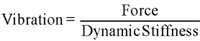
The 1X unbalance force acts through the Dynamic Stiffness of the system to cause 1X vibration:
Because the unbalance is part of the rotor, it rotates at the same speed as the rotor. Thus, the force caused by unbalance is synchronous (1X). A linear system will produce only 1X vibration for a 1X force. However, rotor systems possess nonlinearities, such as strongly increasing fluid-film bearing stiffness at high eccentricity rations. Another source of nonlinearity would be any sudden change in rotor system stiffness, such as due to a rotor-to-stator rub or looseness in the support system. These nonlinearities can generate harmonics of 1X vibration, which can sometimes be seen on a spectrum cascade plot when the rotor is at a resonance. During resonance, the higher 1X vibration amplitude can cause the rotor to pass through a higher eccentricity ratio region in a fluid-film bearing , and the sharp increase in stiffness can produce harmonics.
1X rotor vibration appears as a dynamic load in the bearings. The bearing stiffness and damping transmit this load into the bearing support structure and machine casing, which are part of the extended rotor system. This system will have vibration modes that include the rotor and the machine casing. These modes may be in phase, where rotor and casing move approximately together, or out of phase, where rotor and casing move approximately opposite to each other. The amount of casing vibration will depend on several factors, including the relative masses of the rotor and casing , the stiffness of the bearings, the stiffness of the casing, and the stiffness of the casing mounting and foundation.
The masses, damping, and stiffnesses of the bearing, and mounting combine into the Dynamic Stiffness of the overall rotor support, and it is this Dynamic Stiffness that will determine the relative amounts of shaft and casing vibration excited by the unbalance.
A high ratio of casing mass to rotor mass will usually result in low casing vibration. High pressure compressors and the HP unit of steam turbines fall into this category, Because of the high casing mass, vibration in these machines is best measured using shaft relative transducers.
A lower ratio of casing mass to rotor mass, or a soft support, is likely to produce significant amounts of both shaft relative and casing vibration, which requires casing transducers in addition to shaft relative transducers move with the casing or bearing housing; if the rotor and casing are vibrating in phase, shaft relative vibration may be low, even through shaft absolute vibration may be high. If the rotor and casing are vibrating out of phase, then measured shaft relative vibration may be high, even through shaft absolute vibration may be low. For this reason, casing measurements should be used with shaft relative measurements to provide a complete picture of system vibration.
Aeroderivative gas turbines have low casing mass to rotor mass ratios and relatively flexible casing and supports. They also have rolling element bearings that provide high transmissibility of rotor vibration to the casing. The casings on such machines, due to their flexibility, may possess several modes of casing vibration, and casing transducers must be carefully positioned to avoid nodal points.
When an unbalanced rotor is highly loaded in a fluid-film bearings (perhaps due to misalignment), it operates at a very high eccentricity ratio. The bearing stiffness can become quite high and transmit rotor vibration very easily to the machine casing. At the same time, the high bearing stiffness can suppress the vibration of the rotor. When this occurs, shaft relative rotor orbits will be small and 1X casing vibration will be large.
Similarly, rolling element bearings, because of their extremely high stiffness, strongly suppress shaft relative rotor vibration near the bearings (although midspan shaft relative vibration can be quite large) and transmit vibration directly to the casing. A rolling element bearing machine with a rigid rotor behaves as through the casing and rotor are combined into a large, lumped mass with an unbalance. The resulting casing vibration depends to a great deal on the stiffness of the casing structure and the stiffness of the machine mounting. Very stiffly mounted machines have low levels of measurable 1X casing vibration even through internal dynamic forces and stresses may be high.
Stress and Damage
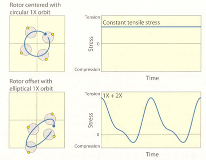
If a rotor centerline moves in a 1X, circular orbit centered on the rotor system axis, the rotor will maintain a constant deflection shape as it rotates. To an observer rotating with the shaft, the rotor will appear to be statically deflected. Under this condition, all areas of the rotor surface will see no change in stress.
A static radial load (either from a process load or the gravity load on a horizontal rotor) will deflect the rotor and produce 1X stress cycling. The constant stress due to the 1X, circular orbit is added to the alternating stress due to the static radial load deflection. If the orbit is elliptical, an additional 2X component of stress may appear. As the size of the orbit increases, the alternating component of the stress also increases. Add any nonsynchronous vibration, and it is easy to see that a typical rotor operates in a very complicated stress environment.
The nominal stresses due to bending of the rotor are increased by various stress concentration factors, such as diameter changes, keyways, (drilled) holes, shrink fits, surface finish defects, slag inclusions, and corrosion. Thus, rotors that experience large radial loads and high 1X vibration due to unbalance are at increased risk for crack initiation and fatigue failure.
Unbalance –induced vibration can damage couplings. The bending of the rotor due to unbalance increases stress on rigid, diaphragm, and disk pack couplings, and increases wear in gear couplings.
1X vibration can also excite casing and piping resonances if their natural frequencies coincide with running speed. The high stresses caused bye the resonance response can cause fatigue failure of either the casing or the piping. In one example, a poorly supported steam injection pipe attached to a gas turbine experienced large, 1X excitation of the resonance vibration during startups and, to a lesser degree, broadband rumble excitation of the resonance at running speed. The combination caused catastrophic fatigue failure of the pipe.
High 1X vibration can cause the rotor to contact stationary parts in the machine, a condition called rub. The rub is most likely to occur during a resonance and can damage seals, which can reduce efficiency.
1X Bode plot from a cold startup of a compressor with excessive unbalance. As the rotor approached the first resonance, a simple bending mode shape, it contacted a midspan seal, producing a rub. The effect of the rub is visible in the truncated resonance of the amplitude plot and the high rate of change of phase. The measurement probe was located near one of the bearings in this two bearing machine, so the midspan amplitude, where the rub occurred, was much larger than that shown on the plot.
Other Things That Can Look Like Unbalance
There is a temptation to view any high 1X vibration problem as an unbalance problem. Unfortunately, there are many conditions that can generate 1X vibration or indirectly cause an unbalance in the rotor. If the true root cause of the problem is not found, then balancing the machine may seem to be the only solution. But the symptoms will probably return, and the potentially damaging operating condition will continue. For example, a cracked rotor, because of crack-induced rotor bow, can look like an unbalance problem. But, balancing a cracked rotor will only temporarily address the symptoms of the problem, and the real root cause will remain.
If a machine does not balance or stay in balance after three (presumably correct) attempts at balancing, then the root problem is probably not simple unbalance. The problem lies elsewhere, and further investigation is warranted.
Many of the following malfunctions have one thing in common, a significant response at slow roll speed. Any 1X response at slow roll speed must be due to something other than unbalance: runout, a permanent bow in the rotor, severe misalignment, a coupling problem, etc.
Runout
When mechanical runout is present, then the distance from the rotor surface to the probe will change as the rotor rotates about its geometric center; even through the rotor centerline does not move, the transducer signal is interpreted as vibration. Mechanical runout includes the effects of surface machining errors, irregularities due to damage, and rotor bow. It can consist of 1X (if the surface is circular and offset from the rotor axis), 2X (if the rotor is elliptical in cross section), higher orders, or a combination of frequencies.
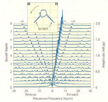
Scratches in the rotor surface viewed by the probe are another form of mechanical runout. Scratches will produce negative-going voltage spikes (and sometimes positive-going spikes if there is material displacement, not just removal) on the transducer signals. The spikes produce recognizable orbit characteristics: a scratch will produce spikes on an unfiltered orbit that usually point away from the probes. A single scratch on the rotor will produce a 1X component and its harmonics in the vibration signal, and they will be visible in the spectrum over all speeds. If a shaft has multiple scratches, it is possible for two scratches to affect two probes simultaneously. When this happens, one spike will appear on the orbit that moves away from both probes (but not directly away from either), and two more will appear that move directly away from each probe. The three spikes will be spaced at 90˚ of rotation from each other.
Electrical runout occurs with eddy current transducers when the electrical conductivity or magnetic permeability varies around the circumference of the rotor. These variations are caused by differences in the microstructure of the alloy, due to alloy type, heat treatment, or cold working. Any of these effects can produce a 1X or higher order variation in the probe signal.
Runout always includes a combination of mechanical and electrical runout. Its primary characteristic is that it is constant in amplitude, even down to slow roll speed, as long as the probe looks at the same circumferential path. Unbalance force, through, is proportional to the square of rotor speed, and path. Unbalance force, through, is proportional to the square of rotor speed, and it will not produce any detectable dynamic 1X rotor response at slow roll speed.
Rotor Bow
A rotor that is bent, or bowed, will produce 1X vibration, but unlike unbalance, it will produce a 1X response at slow roll speed.
A thermal rotor bow can develop while a machine is running. If a hot spot develops on one side of a rotor, that part of the rotor will expand. Because of the one-sided thermal growth, the rotor will develop a bow, which will change the 1X vibration response. If the source of the local heating is removed, then the thermally induced bow will disappear, unless the area has exceeded the yield limit of the material.
Electrical Noise in the Transducer System
Turbogenerator sets operate either at line frequency or at some submultiple of line frequency, depending on the number of poles in the generator. A 2-pole generator will operate at 3600 rpm (60Hz) or 3000 rpm (50 Hz). If power line noise couples into the transducer signal line, then a line frequency component will appear in the vibration signal. This kind of noise has been mistaken for 1X rotor vibration. This can be checked by looking at a spectrum cascade plot during a startup or shutdown. As rotor speed changes, the spectrum line of the electrical noise remains constant in frequency while the 1X rotor frequency changes with speed.
Coupling Problems
Certain types of coupling problems can produce 1X vibration. If the rotor axes of two rigidly coupled machines are offset from each other(parallel misalignment), then, when the machines rotate, a cranking effect will produce 1X vibration in one or both machines. An off-center coupling bore or off-center coupling bolt circle will also produce this kind of 1X cranking action. While unbalance-induced 1X vibration will continue at slow roll speed.
Gear couplings depend on lubricated slippage of the coupling elements for their operation. If a gear coupling should lock up, a sudden change in 1X vibration can take place, along with a change in average shaft centerline position.
Shaft Crack
As a shaft crack propagates across the rotor, the rotor bending stiffness decreases in the vicinity of the crank. Thus, the rotor is less able to resist the dynamic forces that try to deform the rotor and will usually bow as the crank develops. Because the bow moves rotor mass away from the rotor axis, the effective heavy spot of the rotor changes. The crack-induced bow changes the 1X vibration response of the machine.
Shaft cracks usually cause changes in 1X amplitude or phase over time. In the first weeks to months of crack propagation, the 1X response will usually change slowly. The changes in 1X vibration may be mistaken for simple unbalance. While balancing may reduce the vibration due to the crack-induced bow, the root cause problem still remains, and the 1X response will change again.
If the crack is well developed, the large amplitudes of vibration associated with response can plastically deform the rotor in the vicinity of the crack, suddenly changing the bow, 1X slow roll vectors, and the effective heavy spot. Balancing calculations based on shutdown data may not be correct after the rotor experiences high amplitude response during startup. In this scenario, the rotor will have an erratic response to repeated balancing attempts.
Loose Part or Debris
If a part shifts position on the rotor, or debris shifts position in the rotor, the unbalance distribution and the resulting 1X vibration response of the rotor will change. Such a change can happen occasionally(for example, during a startup or shutdown), intermittently, or continuously.
A rotor disk or thrust collar that has become loose may rotate on the rotor, Under some circumstances, a machine component can also move axially. Most likely, the part will slip intermittently whenever the applied torque exceeds the friction at the rotor interface. Such a change in position will produce a step change in 1X vibration that could be detected on an AHT or acceptance region plot. If the part slips during a startup or shutdown, the observed vibration will be different when compared to previous data. Note that the movement of the part might actually reduce 1X vibration if the parts moves to a position where its unbalance partially or completely cancels the rotor unbalance.
Catastrophic failure of a component, such as a broken turbine blade, will also produce a step change in 1X vibration, but that is likely to be of much larger magnitude than what would be produced by a shift in position of a rotor part. If the friction between the part and the rotor is low enough, the part may slip on the rotor and rotate more slowly than the rotor. The unbalance of the loose part will continuously change the effective unbalance of the rest of the rotor. This case will be discussed in more details below.
Fluid or debris can become trapped inside a rotor. When the rotor is shutdown, the debris can shift position, changing the unbalance of the rotor. In one case, a 6 m (20 ft) diameter, 300 kW (400 hp), 880 rpm induced-draft fan exhibited a recurring unbalance problem. Over a period of two years, the fan was balance 24 times! Finally, a new consultant was called in, and he discovered that dirt was trapped in the hub of the fan. Every time the fan was shut down for balancing, the dirt shifted position, rendering the balance shot useless. Once the fan was cleaned and sealed, the problem disappeared.
In another case, the LP shaft borehole plug of a 300MW steam turbine generator came loose and settled inside the turning gear ring. Each time the turbine was stopped, it settled in a different position. It was only when the turning gear was removed to facilitate alignment that the troubling unbalance problem was solved.
Rub
If a rotor begins to rub lightly on the stator once per turn, the friction at the contact point will cause local heating and bow and transfer energy of rotation to lateral vibration. Thus, the 1X vibration amplitude and phase will change once the rub starts. Over time, the rub may wear away part of the contacting element, and the rub-induced 1X vibration changes may become smaller or disappear.
Under rare circumstances, it is possible to develop a light rub that produces a continuous change in amplitude and phase while the machine is operating in a steady state condition. This type of rub can produce circles on a polar trend plot, with a cycle time of minutes to hours. Rub can also modify the spring stiffness of the rotor system and increase or decrease vibration.
Changes in Spring Stiffness
Changes in any of the rotor parameters (mass, damping, spring stiffness, lambda, and rotor speed) will change the Dynamic Stiffness and the 1X vibration response of the rotor. The term that is most likely to change, the spring stiffness term, K, can be affected by many different rotor malfunctions.
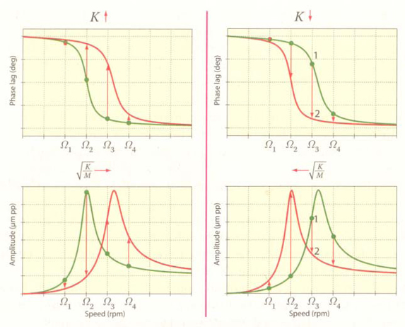
When a rotor operates near a response, changing K can increase or decrease 1X vibration amplitude, depending on whether the rotor operates above or below resonance. A decrease in spring stiffness will always increase the 1X phase lag near a response, and vice versa.
Thus, an increase in 1Xvibration amplitude can look like an unbalance problem when the real problem may be a reduction in rotor system spring stiffness due to a deteriorating foundation, a loose foundation bolt, a change in eccentricity ratio in a fluid-film bearing(possibly due to misalignment), or even a shaft crack. If a spring stiffness increase shifts a resonance closer to running speed, vibration may also increase.
Electric Motor Related Problems
Electric motors, because of their construction, may become unbalanced in normal operation due to shifting winding and loosened wedges. However, various induction motor malfunctions can also produce 1x vibration at near 1X frequencies.
The rotor in an electric motor is built from a set of thin, insulated sheets of metal(laminations) that are stacked together along the rotor. If the insulation breaks down, or if the laminations become smeared due to rotor/stator contact, then adjacent laminations can come into electrical contact and larger eddy currents will circulate in the sheets. This condition is called shorted rotor iron. Because of the resistivity of the lamination metal, the eddy currents dissipate energy, and, because the currents act locally, a local hot spot can form in the region of the contact. Because of thermal expansion, the rotor will tend to bow in the direction of the hot spot and create a temporary unbalance.
The currents in the rotor are highest during startup of the motor, when torque requirements are highest, causing maximum heating. Thus, the unbalance due to the thermal bow caused by smeared rotor laminations will usually be highest immediately after startup and decrease as the motor reaches equilibrium temperature.
The kind of unbalance can also be load related. If smeared rotor laminations are the problem, then reducing the load on the motor should cause a decrease in the 1X vibration response of the motor. Note that, if the location of the shorted rotor iron is opposite to the motor. Note that, if the location of the shorted rotor iron may reduce the unbalance. Under this circumstances, reducing load might increase the 1X vibration.
A broken rotor bar in an induction motor does not carry current. Because of this, the rotor will be cooler on that side and bow away from the broken bar. This bow creates an unbalance that will also tend to be load dependent.
In addition, the bow due to the broken rotor bar will create an uneven air gap between the rotor and the stator. The overall effect will be to modulate the amplitude of the 1X vibration of the rotor at a frequency equal to the number of poles of the motor times the slip frequency.
Two tests are helpful, but not conclusive, in diagnosing a broken rotor bar. Cutting power to the motor should cause the beat frequency to immediately disappear, and a load change should change the amplitude of the modulated 1X vibration.
Eccentric rotor iron will produce a 1X rotor vibration. But the interaction of the rotor with the rotating stator magnetic field will produce a modulation of 1X vibration similar to that produced by a broken rotor bar. Cutting power will cause the modulation to disappear, confirming that the problem is not a simple unbalance problem.
If line frequency electrical noise gets into a transducer system, then a 60 Hz frequency will appear in the signal. If the machine train is driven by a 2-pole induction motor, then the line frequency will be only slightly above the 1X frequency. With poor spectral resolution, it may not be possible to separate the line frequency from the rotor frequency. Depending on the signal to noise ratio, the 1X vibration may appear to be modulated at a beat frequency equal to the slip frequency, which is the difference between the rotor speed and twice the line frequency divided by the number of poles.

Procedure for Experiment A -
Step 1: Select the radius (say 25 mm).
Step 2: Select the unbalance mass (say 25 gram).
Step 3: Select the RPM (say 1000).
Step 4: Press the START button and wait for the system to reach the steady state speed of selected RPM. It will take about 10 seconds.
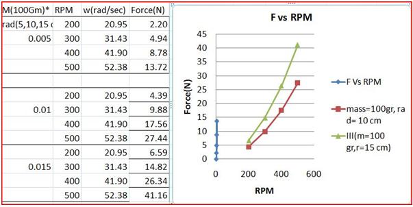
Step 5: Press the APPLY button. This will result in display of force (N) in Newton in the box provided. This is the actual force of unbalance due to the selected radius and mass at the selected RPM. This is also plotted on the graph of F(N) Vs RPM.
Step 6: Now stop the experiment by pressing the STOP button.
Step 7: Repeat the steps from (iii) to (vi) with another RPM (say 2000).
Step 8: Continue for all values of RPM.
Step 9: Study the behavior of the graph F(N) Vs RPM. Try to establish a relationship between F(N) Vs RPM based on the results of the experiment and the plotted graph.
Step 10: Use a curve fitting method / software to establish this relationship.
Procedure for Experiment B -
Step 1: Select the radius (say 25 mm).
Step 2: Select the RPM (say 1000).
Step 3: Select the unbalance mass (say 25 gram).
Step 4: Press the START button and wait for the system to reach the steady state speed of selected RPM. It will take about 10 seconds.
Step 5: Press the APPLY button. This will result in display of force (N) in Newton in the box provided. This is the actual force of unbalance due to the selected radius and mass at the selected RPM. This is also plotted on the graph of F(N) Vs RPM.
Step 6: Now stop the experiment by pressing the APPLY button.
Step 7: Repeat the steps from (iii) to (vi) with another RPM (say 50 gram).
Step 8: Continue for all values of mass.
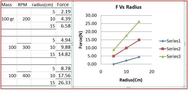
Step 9: Study the behavior of the graph F(N) Vs unbalance mass. Try to establish a relationship between F(N) Vs unbalance mass based on the results of the experiment and the plotted graph.
Step 10: Use a curve fitting method / software to establish this relationship.
Sample Output -


1. What is static unbalancing condition?
2. What is dynamic unbalance condition?
3. What is the effect of statically unbalanced shaft?
4. How do you diagnose static unbalance?
5. How do you judge the severity of static unbalance?
6. Which factors affect the static unbalance force?
ANSWER -
1. Static Unbalance - In rotation, Due to unbalance when the mass/inertia axis is parallel to Shaft axis then it is called as Static Unbalance. A single unbalance acting at the centre of gravity is static unbalance. It occurs frequently in disc-shaped rotors.
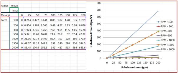
Static unbalance exists when the rotor has one heavy spot. When such a rotor is suspended the heavy spot will tend towards the bottom. This means static unbalance can be determined without rotation of the wheel. The unbalance force is given by:
F = mrω2 where
F = Unbalance force
M = Unbalance mass
r = Distance between unbalance mass and the centre of the object
ω = Angular velocity of the rotor
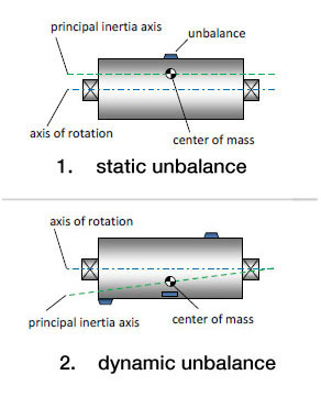
2. Dynamic Unbalance - In rotation an unbalance when the mass/inertia axis does not intersect with shaft axis then it is called Dynamic Unbalance. Combination of static and couple unbalance is dynamic unbalance. It occurs virtually in all rotors. With dynamic unbalance the rotor has two heavy spots diagonally opposed. If such spots are equally heavy, they compensate for each other when the wheel does not rotate.
3. Effects of Static Unbalance -
a) Vibration
b) Noise
c) Decrease in life of bearings
d) Unsafe work conditions
e) Reduced machine life
f) Increased maintenance
4. Diagnosing static unbalance - Unbalance is the most common rotor system malfunction. Its primary symptom is 1X vibration, which, when excessive, can lead to fatigue of machine components. In extreme cases, it can cause wear in bearings or internal rubs that can damage seals and degrade machine performance. Usually, whenever increased 1X vibration is detected, the immediate suspect is unbalance. However, because there are many other malfunctions that produce 1X vibrations, many machines have been balanced only to have the real root cause problem reemerge. Thus, it is important to properly diagnose unbalance and the other malfunctions that produce 1X vibration.
If a machine does not balance or stay in balance after three (presumably correct) attempts at balancing, then the root problem is probably not simple unbalance. The problem lies elsewhere, and further investigation is warranted.
One way is to go for eliminating other malfunctions causing 1X vibration. Other malfunctions such as runout, a permanent bow in the rotor, severe misalignment, a coupling problem, etc. Many of these malfunctions have one thing in common, a significant response at slow roll speed. Any 1X response at slow roll speed must be due to something other than unbalance.
6. The factors which affect static unbalance force are
a) The unbalance mass, m.
b) The distance of unbalance mass from rotational axis, r.
c) The angular velocity of the rotor, ω.

- ANSI S2.2-1959 (R 1990) American National Standard Methods for the Calibration of Shock and Vibration Pickups.
- ANSI S2.11-1961 (R 1986) American National Standard for the Selection of Calibrations and Tests for Electrical Transducers Used for Measuring Shock and Vibration.
- ANSI S2.10-1971 (R 1990) American National Standard Methods for Analysis and Presentation of Shock and Vibration Data.
- ANSI S2.17-1980 (R 1986) American National Standard-Techniques of Machinery Vibration Measurement.
- ANSI S2.7-1982 (R 1986)(ASA 42) American National Standard-Balancing Terminology.
- ANSI S2.38-1982 (R 1990) American National Standard-Field Balancing Equipment-Description and Evaluation.
- ANSI S2.42-1982 (R 1990) American National Standard-Procedures for Balancing Flesible Rotors.
- ANSI S2.40-1984 (R 1990) American National Standard-Mechanical Vibration of Rotating and reciprocating Machinery-Requirements for Measuring Vibration Severity.
- ANSI S2.43-1984 (R 1990) American National Standard-Criteria for Evaluating Flexible Rotor Balance.
- ANSI S2.41-1985 (R 1990) American National Standard-Mechanical Vibration of Large Rotating Machines With Speed Range from 10 to 200 rev/s-Measurement and Evaluation of Vibration Severity in situ.
- ANSI S2.60-1987 American National Standard-Balancing Machines-Encloseres and Other Safety Measures.
- ANSI S2.19-1989(ASA 86) American National Standard-Mechanical Vibration-balance Quality Requirements of rigid Rotors, Part1: Determination of permissible residual Unbalance.
- ANSI S2.61-1989 American National Standard Guide to the Mechanical Mounting of Accelerometers.
- API 670. American Petroleum Institute. Non-contact Vibration and Axial Position Monitoring System.
- API 678. American Petroleum Institute. Accelerometer Based Vibration Monitoring System.
- API 541. American Petroleum Institute. Maximum Permission Vibration for Form-wound Squirrel-cage Induction Motors.
- Compressed Air & Gas Institute. In Service Vibration Standards for Centrifugal Compressors.
- Bently Nevada Seminar. Machine Protection Seminer, Bently Nevada, Minden, Neveda.
- Michael P. Blake and William S. Mitchell. Vibration and Acoustic Measurement Handbook, Spartan Books, 1972.
- Heinz P. Bloch and Fred K. Geitner. Machinery Failure Analysis and Troubleshooting. Gulf Publishing Company, 1986.
- Simon Braun. MSA-Mechanical Signature Analysis. American Society of Mechanical engineers (ASME), 1983.
- Jens T. Broch, Mechanical Vibration and Shock Measurements, 2d ed., 3rd impression, Bruel & Kjaer, Denmark, April 1984.
- Bruel & Kjaer Seminar. Modern techniques of Machine Vibration Analysis, Bruel & Kjaer, Naerum, Denmark.
- Bruel & Kjaer, Vibration Analysis of Machinery, Bruel & Kjaer, Naerum, Denmark.
- Bruel & Kjaer, Digital Signal Analysis Using Digital Filters and FFT Techniques. Bruel & Kjaer, Naerum, Denmark, January 1985.
- Ralph T. Buscarrello. Practical Solutions to Machinery and Maintenance vibration Problems. Update International, Lakewood, Colo.
- Edgar J. Gunter. Selected Papers on Field Balancing of Rotating machinery-Advanced Theory and Techniques. Vibration Institute, Willowbrook, Ill, May 1983.
- Cyril M. Harris and Charles E. Crede. Shock and Vibration Handbook, 2d ed., McGraw-Hill, New York, 1976.
- Cyril M. Harris. Shock and Vibration Handbook, 3d ed., McGraw-Hill, New York, 1988.
- J.P. Den Hartog. Mechanical Vibrations, 4th ed., McGraw-Hill, New York, 1956.
- J.P. Den Hartog. Mechanical Vibrations, 4th ed., Dover Publications, Mineola N.Y., 1985.
- Hewlett-Packard Application Note 243-1. Effective Machinery Maintenance Using Vibration Analysis. Hewlett-Packard Company, Palo Alto, Calif., 1983.
- Hewlett-Packard Application Note 243. The Fundamental of Signal Analysis. Hewlett-Packard Company, Palo Alto, Calif., 1982.
- Robert S. Jones. Noise and Vibration Control in Buildings. McGraw-Hill, New York, 1984.
- J. M. Juran. Quality Control Handbook, 3rd ed., McGraw-Hill, New York, 1979.
- Mechanical Technology Incorporated (MTI). June 1987 Seminar, Rotating Machinery, Vibration Analysis and Diagnostic Techniques. MTI, Latham, N.Y., 1973.
- John S. Mitchell. An Introduction to Machinery Analysis and Monitoring. PennWell Publishing, Tulsa, Okla., 1981.
- John Piotrowski. Shaft Alignment Handbook. Marcel Dekker, New York, 1986.
- Singiresu S. Rao. Mechanical Vibrations. Addition Wesley, Reading, Mass., 1986.
- J.D. Smith. Gears and Their Vibration: A Basic Approach to Understanding Gear Noise. Marcel Dekker, New York, 1983.
- W. Soedel. Vibration of Shells and Plates. Marcel Dekker, New York, 1981.
- Vibration Institute Seminar Procedings. Balancing of Rotating Machinery-Houseton, Texas. Vibration Institute, Willowbrook, III., February 26-28, 1980.
- Vibration Institute Course. Machinery Vibration Analysis I Course-Tempe, Arizona. Vibration Institute, Willowbrook, III., March 1-4, 1988.
- The Balance Quality of Rigid Rotors, ISO DR 1940.
- AD-A171 031, P.D. McFadden. "Examination of a Technique for the Early Detection of Failure in Gears by Signal Processing of the Time Domain Average of the Meshing Vibration." Commonwealth of Australia, 1986, ARL-AERO-PROP-TM-437.
- AD-A182 572, P.D. McFadden. "Interpolation Techniques for the Time Domain Average of the Meshing Vibration Data with Application to Helicoptor Gearbox Monitoring." Commonwealth of Australia, 1986, ARL-AERO-PROP-TM-437.
- AD-A173 851, P.D. McFadden. "Analysis of the Vibration of the Input Bevel Pinion in Ran Wessex Helicoptor Main Rotor Gearbox WAK 143 Prior to Failure." Commonwealth of Australia, 1985, ARL-AERO-PROP-R-169.
- AD-A155 199, P.D. McFadden. "Proposal for Modifications to the Wessex Helicoptor Main Rotor Gearbox Vibration Monitoring Program." Commonwealth of Australia, 1985, ARL-AERO-PROP-TM-422.
- Hydraulic Institute Application Standards B-74-1, 1967.
- S2.5. American Standard Recommendations for Specifying the Performance of Vibration Machines.
- J. I. Taylor. "Identification of Bearing Defects by Spectral Analysis." ASME Publication 79-DET-14, 1979.
- Harvey L. Balderston. "The Detection of Incipient failure in Bearings." Materials Evaluation, Vol. 27, No. 6, June 1969, pp. 121-128.
- De Jongh, Frits M., and van der Hoeven, Pieter, "Aoolication of a Heat Barrier Sleeve to Prevent Syncronous Rotor Instability," Proceedings of the Twenty-Seventh Turbomachinery Symposium, Texas A & M University, College Station (September 1998).
- American Petroleum Institute, Tutorial on the API Standard Paragrapghs Covering Rotor Dynamics and Balancing: An Introduction to Laterral Critical and Train Torsional Analysis and Rotor Balancing, API publication 684(Washington, D.C.: American Petroleum Institute, 1996).
- Muszynska, A, "One Lateral Mode Isotropic Rotor Reponse to Nonsyncronous Excitation," Proceedings of the Course on the Rotor Dynamics and Vibration in Turbomachinery, von Karman Institute for Fluid Dynamics, Belgium (September 1992).
- Machinary Lubrication 5/2005
- http://www.mechanicalengineeringblog.com/tag/looseness/
- http://www.update-intl.com/VibrationBook13b.htm
- http://www.machinediagnostics.com/PDF/Vibration/VibrationGuide.pdf
- http://http//:www.mech.uq.edu.au/courses/mech7350/lecture-notes-in-pdf/mech7350-17-fault-diagnosis.pdf
- http://www.vtab.se/training/vibration-school/mechanical-looseness/?lang=en
- http://www.vibanalysis.co.uk/vibanalysis/looseness/looseness.html