
A pump is a mechanical device where mechanical energy is transformed into hydraulic energy. It is used to transfer liquid from source to destination and circulate liquid around the system. In present days, 20% of world's electrical energy is consumed by use of pumps.
There are many conditions which leads to the failure of a pump. This includes seal related problems(leakages,loss of flushing), pump and motor bearing related problem(loss of lubrication, contamination of oil, abnormal noise), leakages from pump casing very high noise and vibrational levels, or motor related problems. Hence certain measures are required to predict the machinery failure much before it occurs.
Condition Monitoring(CM) is a technique to determine the health and condition of equipment,machines and machining system by observing, checking, measuring and monitoring certain parameters. CM provides information on failures before system is going to fail.
Predictive maintainence does not prevent the failure of a machine and machinery systems but it can predict the possibility of failure by using CM. CM system can only measure the deterioration of the condition. Intervention in the early stages of deterioration is usually much more cost effective and safe than allowing the machinery to fail.

What is a Centrifugal pump?
A centrifugal pump is a rotor dynamic pump that uses a rotating impeller to increase the pressure of a fluid.
- Rotating impeller of the pump increases the velocity of liquid.
- When its flow velocity increases, Kinetic energy is added to the liquid which is later converted to pressure energy partly by increasing the flow area of casing (decreases the velocity).
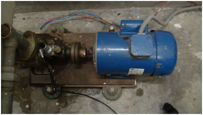
Fig. 1: Centrifugal Pump
Working of Centrifugal pump
- Liquid is forced into impeller.
- Vanes pass kinetic energy to liquid:liquid rotates and leaves impeller.
- Volute casing converts KE to pressure energy.
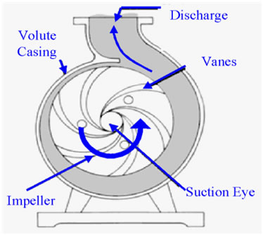
Fig. 2: Schematic diagram of a centrifugal pump
Advantages of centrifugal pump
Centrifugal pumps are used in a wide variety of applications. These machines operate at high speeds and usually are directly connected to the prime mover (or electric motor) so that the transmission losses are small. There are minimum number of moving parts which reduces the maintenance and increase the working time, other advantages of centrifugal pumps (over reciprocating pump) are smaller size and low installation costs.
Problems faced in centrifugal pump
- Wear out of impeller.
- Vibrations
- Leakage along shaft
- Bearing failure
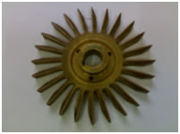
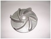
Fig. 3: Normal impellers
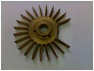
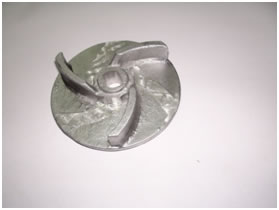
Fig. 4: Defective impellers (Broken vanes)
Various condition monitoring techniques have been developed for determining the health and condition of the equipments and machineries like:
- Temperature monitoring
- Noise monitoring
- Debris monitoring
- Leakage monitoring
- Vibration monitoring
- Motor current signal analysis
Out of all these techniques, vibration monitoring and MCSA are most suitable for detection of faults in centrifugal pumps. Hence these two techniques have been used in this experiment to detect the faults for different types of impellers.
Vibration Monitoring
It normally consists of vibration measurement, data collection and data analysis. It is basically monitoring the response of the system or machine to internal & external forces being applied. The response is measured by a transducer (like accelerometer) at the pump and motor bearings and is passed through data cable to the analyzer for interpretation. Vibration transducer transforms the vibrating motion (displacement, velocity, acceleration) to electrical signal form.
Motor current monitoring
It is a technique used for analysis of dynamic and energized system. It is an online/offline analysis technique which includes instantaneous current measurement, FFT of current, etc. to detect fault in motor driven machinery while it is operating. It uses Hall Effect sensor (as a transducer) and analyzer for analysis. By this analysis the faults (like broken rotor bars, bent shaft, bearing irregularities etc) can be detected.

The objective of this experiment is to detect fault in the impeller of a centrifugal pump using vibration analysis and motor current signature analysis(MCSA).

With reference to the aforesaid objectives, the experiments have been performed in the following sequence: A centrifugal pump is run with 24 vanes brass impellers at various conditions (of impeller like non-defective, one vane removed, two vanes removed, three vanes removed). Vibration signal and motor current signals are recorded during operation/working condition and the data is analyzed by the PULSE analyzer.
Equipment Used
- Accelerometer (PCB, 353B33)
- Hall Effect Sensor (TektronixA621)
- PULSE analyzer (Bruel & Kjaer)
- Centrifugal pump coupled with induction motor (1 hp, 1450 RPM, 240 V, make- Crompton Greaves)
Impellers used in pump are made of brass; with external diameter 100 mm; width 10 mm; vane length 25 mm and number of vanes is 24.
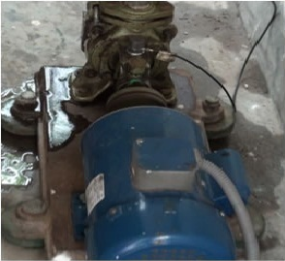
Fig. 5: Accelerometer mounted on the pump.
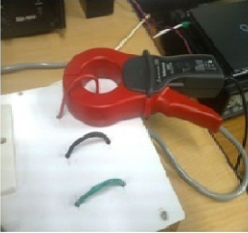
Fig. 6: Hall-effect Sensor
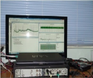
Fig. 7: Pulse Analyser
Experimental Procedure
- Firstly, the water tank was filled with water to such a height so that the inlet pipe is just below the water level. Then the accelerometer was placed on the casing of the pump (as shown in fig. 5) to measure the vibration and it is connected to analyzer through the data cable (B&K). Hall Effect Sensor (Tektronix A621) (as shown in fig. 6) is connected to the analyzer through the data cable to measure the instantaneous motor current.
- The centrifugal pump was switched on and readings were taken under different working conditions of impeller like normal impeller (all vanes present), one vane broken impeller, two vanes broken impeller, three vanes broken impeller sequentially.The PULSE analyzer (as shown in fig. 7) is used to analyze the vibration signal and motor current signal.
- Four no. of tests have been performed with different impeller conditions (two experiments have been done with each impeller condition for repetition). For each test, current and vibration signal data were collected. For each of the signal data the following were recorded
- Recording data for 10s
- Time domain data for 4 s for both current and vibration signal
- FFT Spectra upto 1.6 kHz forboth current and vibration signal
Using the recorded time history data, maximum, minimum, mean, RMS, standard deviation, variance, skewness, kurtosis, crest factor, form factor were calculated. FFT (both current and vibration) analysis is done for getting rotating speed (RPS) of pump, Vane pass frequency (VPF), Sidebands (SBs) around VPF and their respective amplitude (in dB).
Experiments
Four different sets of data have been obtained from each test. The result of each set is presented as follows. The following results were taken at the full flow rate of the pump.
The data, which was collected with the help of an accelerometer, were analyzed using PULSE and the vibration spectra were obtained.
The vane pass frequency (VPF) has been found from the vibration spectrum and compared with their corresponding amplitudes (in dB) and their sidebands, SBs (at VPF ± RPS) for different impellers. VPF is calculated by the product of RPS and number of vanes of the impeller. The VPF and its sidebands are shown on the respective vibration spectra for each test.

1. What are the benefits of Condition Monitoring?
2. What is cavitations in pump?
3. What is VPF of a pump?
4. What is a function of an impeller?
5. What is measured by hall effect sensor?

Books
- Fluid Mechanics (2nd Edition) by A.K.Mohanty (PHI), 2010.
- Practical Machinery Vibration Analysis and predictive Maintenance by Paresh Girdhar, Elsevier Publication, Burlington, 2004.
- Digital Signal Processing, using MATLAB and Wavelets by Michael Weeks, Infinity Science Press LLC, Hingham, USA.
Videos