
The PUMA 560 is a industrial robot arm with six degrees of freedom and all rotational joints. In this experiment at first a brief theory about PUMA 560 robot is presented in the theory section. The theory for mathematical computations was obtained from a wide variety of sources encompassing books, papers and internet. In simulation section a virtual model is developed in javascript program which is used to investigate the forward kinematics problem. For more information on other aspects of PUMA 560 and robotics visitors are advised to follow the references.
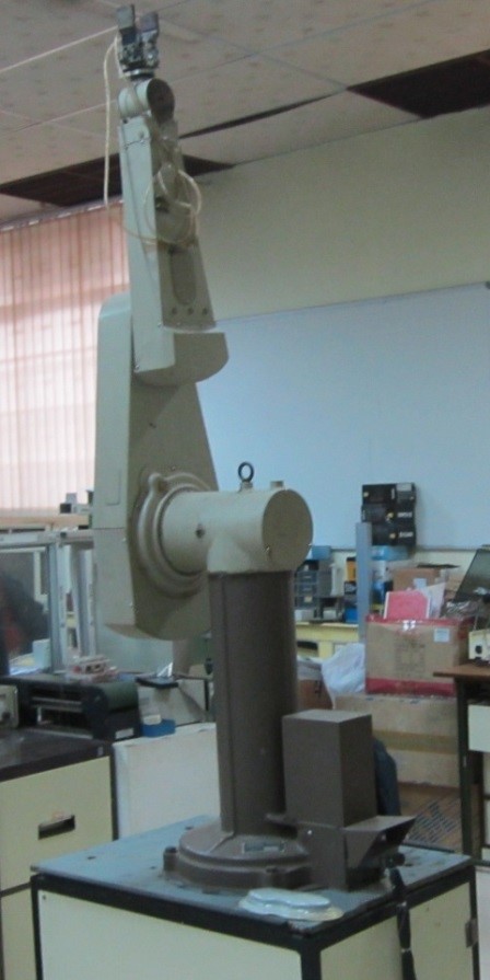
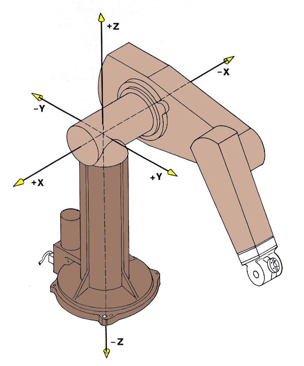
Figure 1: PUMA 560

Theory
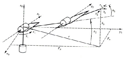
- Programmable Universal Machine for Assembly, more popularly known as PUMA is an industrial robot arm developed by Victor Scheinman at Unimation, in the year 1978. PUMA comes in various makes viz. PUMA 260, PUMA 560, PUMA 761 etc. Figure 2 shows link-frame assignments in the position corresponding to all joint angles equal to zero. Here the frame {0} (not shown) is coincident with frame [1} when is zero. Note also that, for this robot, as for many industrial robots, the joint axes of joints 4, 5, and 6 all intersect at a common point, and this point of intersection coincides with the origin of frames {4}, {5}, and {6}. Furthermore, the joint axes 4, 5, and 6 are mutually orthogonal. This wrist mechanism is illustrated schematically in Fig.4. In this experiment forward kinematics of PUMA 560 is described through a virtual model. The forward kinematics problem is concerned with the relationship between the individual joints of the robot manipulator and the position and orientation of the tool or end effector.
General Terminology in Robotics:
Workspace:
The reachable workspace of a robot's end-effector is the manifold of reachable frames.
Accuracy:
Accuracy refers to a robot's ability to position its wrist end at a desired target point within the work volume, and it is defined in terms of spatial resolution. It depends on the technology and the control increments.
Repeatability:
Repeatability is a statistical term associated with accuracy. If a robot joint moves by the same angle from a certain point a number of times, all with equal environmental conditions, the target is always missed by a large margin. If the same error is repeated, then we say that the repeatability is high and the accuracy is poor.
Safety:
The ability to reduce the human-robot impact force and ensure human safety is a fundamental requirement for human-friendly robots.
Forward Kinematics :
Forward kinematics (FK) mainly deals with constructing a Denavit-Hartenberg (D-H) transformation matrix with Puma's parameters obtained from a D-H parameter table shown below:
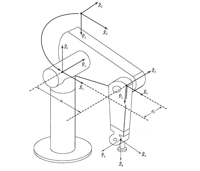
Figure 2: Kinematic parameters and frame assignments for the PUMA 560 manipulator.
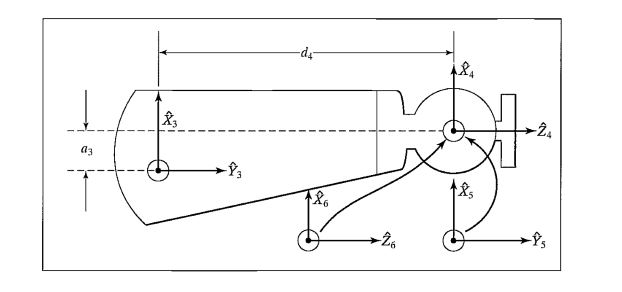
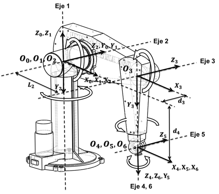
Figure 3: Kinematic parameters and frame assignments for the forearm of the PUMA 560 manipulator.
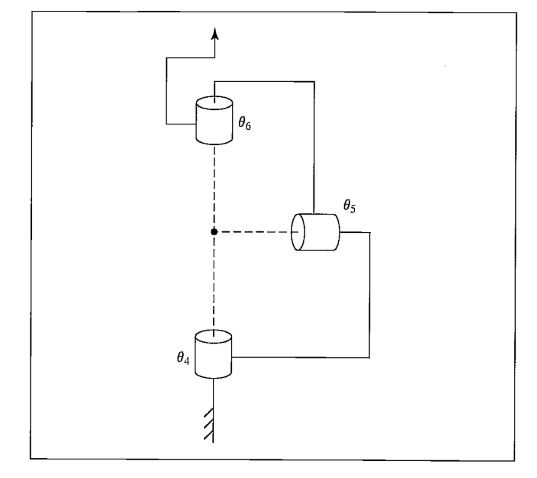
Figure 4: Schematic of a 3R wrist in which all three axes intersect at a point and are mutually orthogonal.
Table 1. Puma 560 D-H parameter table
| `Link_i` | `alpha_(i-1)` | `a_i-1`(m) | `d_i`(m) | `theta_i` |
|---|---|---|---|---|
| 1 | 0 | 0 | 0 | `theta_1` |
| 2 | -90 | 0 | 0 | `theta_2` |
| 3 | 0 | `a_2` | `d_3` | `theta_3` |
| 4 | -90 | `a_3` | `d_4` | `theta_4` |
| 5 | 90 | 0 | 0 | `theta_5` |
| 6 | -90 | 0 | 0 | `theta_6` |
Transformation matrices of six joints for Puma 560 robot
`T_1 = [[cos \(theta_1\),-sin \(theta_1\),0,0], [sin \(theta_1\), cos \(theta_1\),0,0], [0,0,0,1], [0,0,0,1]]` `T_2 = [[cos \(theta_2\), -sin \(theta_2\),0,0], [0,0,1,0], [-sin \(theta_2\),-cos \(theta_2\),0,0], [0,0,0,1]]`
`T_3 = [[cos \(theta_3\),-sin \(theta_3\),0,a_2], [sin \(theta_3\),cos \(theta_3\),0,0], [0,0,1,d_3], [0,0,0,1]]` `T_4 = [[cos \(theta_4\),-sin \(theta_4\),0,a_3], [0,0,1,d_4], [-sin \(theta_4\), -cos \(theta_4\),0,0], [0,0,0,1]]`
`T_5 = [[cos \(theta_5\), -sin \(theta_5\),0,0], [0,0,-1,0], [sin \(theta_5\),cos \(theta_5\),0,0], [0,0,0,1]]` `T_6 = [[cos \(theta_6\),-sin \(theta_6\),0,0], [0,0,1,0], [-sin \(theta_6\),-cos \(theta_6\),0,0], [0,0,0,1]]`
Final Transformation Matrix `T = T_1*T_2*T_3*T_4*T_5*T_6`
The orientation and position of the end effector with reference to the base coordinate is obtain from the final matrix `T = [[n,s, a,p], [0,0,0,0]]=[[n_x, s_x, a_x, p_x], [n_y, s_y, a_y, p_y], [n_z, s_z, a_z, p_z], [0,0,0,1]]`
Puma kinematic diagrams
Simplified drawing of first three links of Puma 560 with transformation frames appropriately


- To identify the geometric relationship between input and output motion parameters of PUMA 560 robot manipulator.
- Formation of the transformation matrix though which a relationship is established between different links of the manipulator.
- Simulate the robot motion for various inputs of the joint angular value.
- To have a brief idea about the workspace through a 3D graph plot of manipulator position for various inputs.

- Insert different values of `theta` within the joint range as prescribed in theory part and then click ok to get the output orientation and position of the end effector.
- To see the individual movements of the links drag the sliders on the controller panel.
- The Transformation matrix for a particular position and orientation can be obtained either through input panel or via the controller.
- Manipulator position is shown in a 3D graph for every submission of joint values.
- The view can be rotated about a point by keeping the left mouse button pressed and rotating the mouse.
- The view can be translated by keeping the right mouse button pressed and translating the mouse in the desired direction.
- The scroll button or middle mouse button can be used for zooming.


This program simulates a 6 link 3D Puma Robot using the javascript program. The model and its movement of different links are encoded in javascript language. Model With this program the forward kinematics of PUMA 560 is explained, and simultaneously movements of different joints at a time can be seen. Axis coordinates and orientation are setup according to the theory explained earlier. This program does not allow for the specification of angular speed or acceleration of the arms. Click on the screenshot given below to start the simulation.
Kinematics Panel consists of:
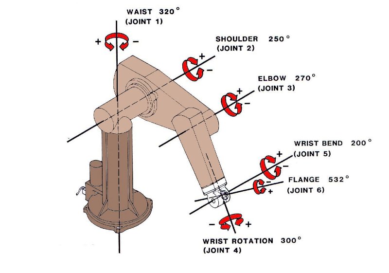
| Angle | Range | DOF |
|---|---|---|
| `theta_1`: 320 | -160 to +160 | Waist Joint |
| `theta_2`: 270 | -225 to +45 | Shoulder Joint |
| `theta_3`: 270 | -225 to +45 | Elbow Joint |
| `theta_4`: 280 | -110 to +170 | Wrist Roll |
| `theta_5`: 200 | -100 to +100 | Wrist Bend |
| `theta_6`: 532 | -266 to +266 | Wrist Swivel |
Click on the screenshot to start the simulation
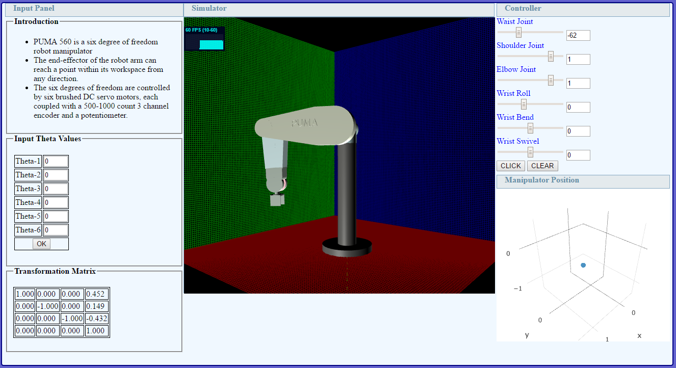
Simulator Screen shot
Click to open the Simulator Tab
Test Your Knowledge!!

- A. K. Mallik, A. Ghosh and G. Dittrich - Kinematic Analysis and Synthesis of Mechanisms, CRC Press Inc. Boca Rato
- A. Ghosh and A. K. Mallik - Theory of Mechanisms and Machines, Affiliated East-West Press (P) Ltd., New Delhi
- Ghosal A (2006) Robotics: Fundamental Concepts and Analysis, Oxford University Press.