

What is Computer Integrated Manufacturing (CIM)?
Computer Integrated Manufacturing (CIM) is the technology for integration of all
the operational and information processing functions in a manufacturing enterprise
ranging from order receipt from customers to design, process planning, material requirement
planning, manufacturing resources planning , purchasing, production planning and control,
marketing and sales etc. The integration of the total manufacturing enterprise is accomplished
through the use of computer and data communication technologies coupled with various managerial
philosophies to improve the organizational and personal efficiencies.
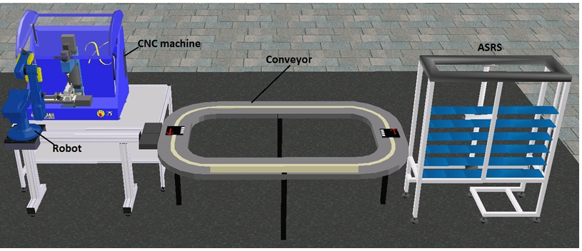
What is CIM cell?
CIM cell is an automated manufacturing system comprising of
- one or more automated processing stations typically computer numerical control (CNC) machine tools,
- one or more equipment for automated material handling and transport such as robots ,conveyors.
- storage devices to store raw materials, work-in-progress and finished products that may include storage racks, and Automated Storage and Retrieval Systems (ASRS),
- one or more quality control equipments such as machine vision system, Coordinate Measuring Machine(CMM), etc., and
- a CIM software for overall integration, planning and control of the various operational and information processing function at individual stations of the CIM cell.
A typical CIM cell
The Figures show the components of some typical CIM cells and their components.

CNC MACHINE:
The machines shown in the cells are typically CNC machines
which can be either a CNC milling machine that is equipped
with an Automatic Tool Changer (ATC) or a CNC lathe that is
equipped with an index able tool turrent. Figures below show two
CNC machines. CNC Milling machines can be employed for two/three
axes machining of plane and sculptured surfaces for various operations
like milling and drilling by using rotating tools. Loading and unloading
of the parts at the CNC machine are carried out automatically using an
industrial robot as shown.
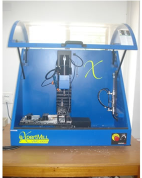

Fig: A CNC milling machine Fig: A CNC lathe machine
ROBOT:
The robots shown in the cells having four to six axes manipulator
as shown in the following figures equipped with a gripper that is capable of automated
material handling tasks such as loading/unloading of parts to/from the machines, storage
and retrieval of parts in/from storage devices, assembling of parts and handling of parts
for quality control.
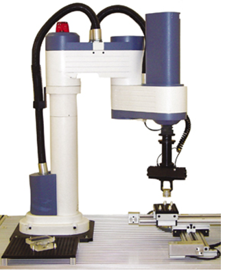

Fig: A four axes SCARA robot Fig: A five axes revolute robot
STORAGE STATION:
A storage station is used to retrieve raw materials
prior to production, store work-in-process inventory, as well as finished
products. The storage stations may use an Automated Storage and Retrieval
System (ASRS) or simply storage racks. The storage and retrieval at such
stations are automated by robot manipulators.
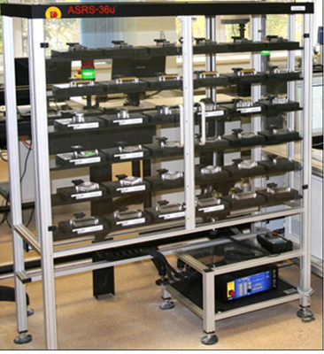
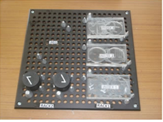
Fig: An Automated Storage and Retrieval System Fig: Storage Rack
QUALITY CONTROL STATION:
The purpose of quality control station is to determine whether
a product meets the quality control specifications as defined prior to the production
process. The quality control stations shown may consist of a machine vision system
equipped with a camera and image processing software or a Coordinate Measuring Machine
(CMM). Handling of the parts at the quality control stations is carried out automatically
using robot. Handling of the parts at the quality control stations is carried out using robot.

CIM SOFTWARE:
It provides a centralized control of on line production operations at
each of the individual station devices of the CIM cell. It sends commands to station devices
for starting and stopping the production and receives responses from the station devices which
enable it to track the flow of parts during a CIM production cycle. It further maintains a database
containing information on the physical and communication control configuration of the CIM cell, bill
of materials used to produce each part, the order specifying the part to be produced, inventory of raw
materials and parts, definition of machines in the CIM cell and manufacturing process that they can
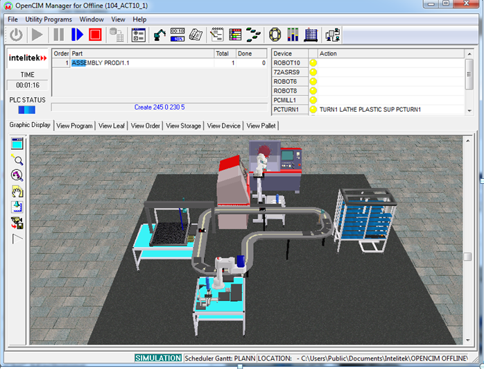
perform and the content of all the storage locations. It further provides a web accessible interface
to remotely access a specific CIM cell and track the production cycle in real time for online tracking
of the CIM production cycleby providing a Graphic Display tab to enables display of the image of a CIM
cell in 3D that can dynamically and accurately simulate the operations of all individual station devices
in the CIM cell, a View Scheduler tab to view the production timing and schedule which is a Gantt chart
utility to display the exact timing and scheduling of the different phases of production,a View Program
tab to view the current production status for viewing the current production work order and track its status,
a View Leaf tab to view the description of the current production activities in the current CIM cell describing
the current operation being performed on each item as well as the operation that will follow immediately, View
Order tab to view a copy of the manufacturing order of the current cell, a View Storage tab to view part location
in the storage for viewing a list of every storage location defined in the CIM system and storage status, a View
Device tab to view device activities at various stations for viewing a list of every robot and machine as well as
a description of the current action being performed,etc..

- To demonstrate the operation of an actual CIM cell by providing remote access to the the operations at different workstations.
- To To demonstrate the parts and production flow as well as interaction between the various components involved in the CIM cell.
- To demonstrate monitoring of production management functions in real time in the CIM cell.

Experimental Setup
The CIM system consists of two cells. Cell 1 is the storage, assembly and quality control station, which consists of the following equipments:
- A storage rack for storing the raw materials, work-in-process inventory as well as finished products,
- An assembly jig for building the assembly,
- A camera and image processing system for automated inspection, and
- A Scorbot robot manipulator.
The Scorbot robot is used for CNC machine loading/unloading tasks,
material handling for storage/retrieval of parts to/from storage as
well as for presenting the part at the quality control station and for assembly.
The manufacturing operations that can be carried out in the CIM system are milling
of plexiglass blocks, assembly operations, material handling between stations and the
quality control of parts by machine vision.
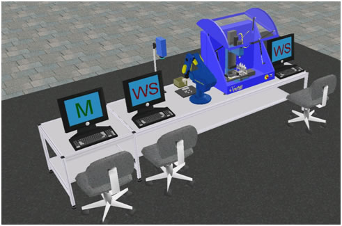
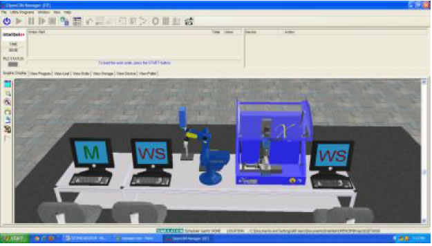
The overall CIM system is run with a supervisory host control system
consisting of two cell work station PC's for the two cells and a host computer.
The host computer allows management of CIM orders and operations via the CIM Manager
- OpenCIM software system architecture. The OpenCIM offers various capabilities like CIM management,
parts definition, order definition, machine definition, automatic CNC programs downloading for CNC machines,
MRP package, 3D graphic animated simulation for on-line tracking of the whole system, reports generator for production
reports, CIM scheduler module (GANNT chart). The CIM Manager software via OpenCIM provides centralized control of
on-line production activities. It sends commands to station devices and receives responses, which enable it to track
the flow of parts during production.

Steps involved:
- Describe the steps for the CIM system start up.
- Describe the steps for remotely monitoring the operations of the CIM cell.
- Describe the steps for the CIM system shut down.
Users, who wish to remotely access the CIM set-up, are required to first book a slot by using the Remote Experiment tab. Next follow the instructions provided in Step II given below.
Steps I and III are instructions meant for the operators who would be present on site and responsible for actually operating the CIM cell in the laboratory.
Step I: Steps for system start up
- Turn on the Mains switch for the compressor on the ground floor.
- Make sure that the power supply to the FMS lab is turned on.
- Turn on the power supply to the UPS of Manager PC, Workstation 1, Workstation 2 and the Robot Controller.
- Turn on the three PCs.
- Turn on the Robot Controller
- Turn on the CNC Controller
- Turn on the Remote Control Switch for the Compressor.
- Open the valve of compressed air supply and make sure that the gauge pressure is 6 bar
- Log in to the Manager PC.
Please follow the safety precautions given below.
Make sure that the Teach Pendent is on the hanger and in Auto Mode, and Emergency Button is not pressed.
Make sure that the Emergency Button of the Robot Controller is not pressed and the Red power LED is ON.
Make sure that four LEDs at the LAN switcher are ON.
Make sure that there are three MILL SUP parts in Rack1.
Make sure that the two XV parts are in Rack2.
Make sure that there is no part in the Jig.
Make sure that there is no part in the Trash bin.
Make sure that there are no parts below the camera and the Table is clean.
Make sure that there is no part in the Robot Gripper.
Make sure that the Robot is in safe place to Home.
Make sure that the air dial indicator on the side of the CNC Mill is not zero.
Make sure that there are three tools in the Tool Changer and one tool inside the Spindle.
Make sure that there is no part in the vise.
Make sure that the vise is Open and has two Aluminium spacer and one plexiglass spacer.
Make sure that the CNC mill is clean.
Make sure that the Emergency Button on CNC Mill is not pressed
Make sure that the spindle speed is CNC ON.
- Log in to the Workstation 1 and Workstation 2.
Steps for loading the Software in Workstation PCs 1 and 2 and the Manager PC
Loading software in Manager PC
- Click on the CIM Manager icon.

- Open CIM Manager Window will be displayed as follows.
Loading software in CIM Station 2
- Click on the Loader of WS2 icon.

- The CIM DDLoader menu will be displayed.
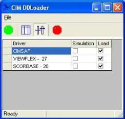
- Click on the Green Button.
- Two softwares will load as follows.
- On the SCORBASE software, click on the Home icon.

- Homing menu will be displayed and the Robot will start its Homing Procedure.
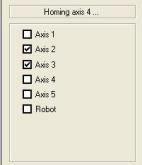
- Wait until all the Boxes are ticked and the Robot has stopped homing.
- Make sure that program ST2 is loaded. If not, load it from Z:\IIT\WS2\ROBOT2 folder
- Station 2 is now ready to run in FMS.
Loading software in CIM Station 1
- Click on the Home icon.

- Machine Home Window will load.
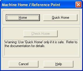
- Click on the Home button.
- The machine will now home all three axes.
- Wait until the homing is completed.
- On the Top Menu, click on File, and START.NC program
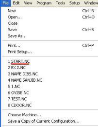
If it is not shown, load it from Z:\IIT\WS1\VMC0600 FOLDER
- START program will load.
- Click on the Green RUN.

- The Run program menu will be displayed.
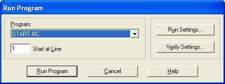
- Click on the Run Program button.
- Please verify the ATC configuration message will be displayed.
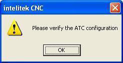
- Click on OK.
- Configure ATC window will be displayed.
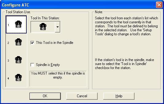
- Look at the Mill and verify that the tool shown on the window is physically present in the spindle.
- Click OK.
- The START program will run.
- A yellow bar will show on top of the software window.

- The Mill is now ready to run in FMS.
- Minimize the Mill software.
- On Desktop, click on the Loader of the WS1.

- The CIM DDLoader menu will be displayed.
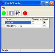
- Click on the Green Button.
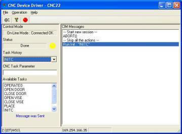
- CNC device driver will be displayed.
- Click on the Green Button.
- CNC device driver will be displayed.
- FMS is now ready to run.
Steps for creating MRP and Manufacturing Order in Manager PC
Go to the CIM Manager PC. For creating an MRP and Manufacturing Order of the different parts to be produced in the CIM cell and running the CIM system, perform the following steps:
- Select IIT from user projects and click on CIM manager icon.
- From the CIM Modes menu, select the Real mode.
- Click on Utility Programs menu from menu bar and select MRP
- Choose the order you want to run by selecting the Part name from the drop-down menu and Enter Required Qty, Priority and Due Date.
- Click Save Order
- Click on the MRP icon
 From the message box with the prompt
 - Click on the manufacturing order tab.
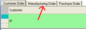
- In the Manufacturing Order window, click the Order you want to run and Part Name. It will change the color to green.
- Next click MO (Manufacturing Order) icon
 on the toolbar.
From the message box with the prompt "Manufacturing Order Done" click OK.
on the toolbar.
From the message box with the prompt "Manufacturing Order Done" click OK. - Save and Exit MRP menu.
Steps for running a CIM production cycle
- From the main screen of the CIM Manager, click Reset Storage icon
 from the tool bar.
 - Click on the Green "START" icon
 on the CIM Manager menu.
 - Make sure that all the devices change from yellow to green.

- At this moment, the program of production is initialized into
the system. Click on the Green Arrow "RUN" icon
 on the main screen to run the production.
 - View the progress of the orders by clicking on the View Program tab.
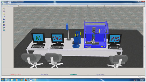
- For Graphic Display of the various operations at the workstation in the CIM cell, click the Graphic Display tab.
- When the order is completed, the CIM Message will appear "Order Has Been Completed"
- Click on the red stop button

- If you want to run a new order, make sure that you replace all the parts back in the correct places in the initial state of storage.
Step II: Steps of using the WebcimViewer for remotely monitoring the operations of the CIM cell
- First download and install the Web Viewer client by simply clicking here . Select run in order to run this program from its current location.

The Web Viewer Client Setup window will be displayed. When the installation is complete, click Finish.
- Select Save in order to save this program to a specified directory
for future installations. 3.Open the Internet Explorer (version 6.0 and higher),
and enter the following IP address in the address field: http://203.110.245.95/WebCimViewer/start.ASP
(Note: The Web Viewer application enables you to remotely access a specific CIM cell and track the production cycle from the various view tabs.) A webpage will be displayed as follows.

- Click Start. The Open CIM Web Viewer appears displaying the Graphic Display Window as shown below with the following tabs to help in tracking the CIM production cycle.
Graphic Display Tab to show a 3D display of the operations being performed in the CIM cell.
View Scheduler Tab to display the scheduler information of the CIM cell.
View Program Tab to display the A-Plan (meaning, the production work order) of the CIM cell.
View Leaf Tab to display the production activities in the CIM cell.
View Order Tab to display the current manufacturing order.
View Storage Tab to display the current location of parts in the CIM cell.
View Device Tab to display the actions performed by system devices.
View Pallet Tab to display the pallets in the CIM cell and the current status of each pallet.
Web Viewer Status Bar to display CIM cell information, such as current status, elapsed time, etc.
View About Tab to display dialog with information about Web CIM Viewer software
and CIM software of the Cell that is currently in view.
For details on how to use the above tabs for tracking the CIM production cycle, please refer to the video tutorials given in the User Guide page.
Step III: Steps for using IP camera for remotely viewing the operations of CNC:
- Open Internet Explorer browser and type http://203.110.245.36 in the address bar.
- Once the page gets loaded, the login window will come up as shown in the figure below.
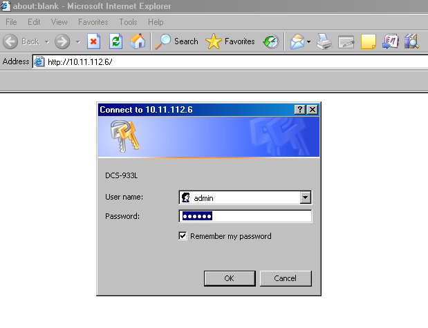
Enter Username: admin
Password: 123456
- Then the IP camera page loads. If you are viewing this page for the first time, it will ask you to install the plugin as shown below.
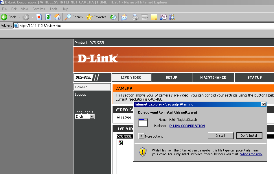
- Click on install and it will install the plugin.
- Then you will be able to view the CIM cell operations through IP camera as shown in the figure below.

Step IV: Steps for system shut down
- Make sure that all the produced parts are removed from the rack and new supplied parts are placed in the rack.
- Make sure that the two XV parts are in their rack positions.
Steps for shutting down the WorkStation 1
- Go to the Workstation 1 PC and Exit from the CNC Device driver.
- In CNCBase software, click on the red stop button and OK.
- Exit the CNCBase software.
- Shut down the PC.
- Turn off the Mill controller.
- Turn off the Workstation 1 UPS.
Steps for shutting down the WorkStation 2
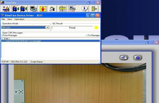
- Go to the Workstation 2 PC and in Scorbase software go to the last subroutine (SHUTDOWN) and run lines 247 and 248 in RUN SINGLE LINE.
- Exit from the ViewFlex.

- Exit from the Scorbase software. Do not save.
- Shut down the PC.
- Turn off the Robot controller.
- Turn off the Robot Controller UPS.
- Turn off the Workstation 2 UPS.
Steps for shutting down the CIM Manager PC
- Go to the CIM Manager PC and exit from the Manager software.
- Shut down the PC.
- Turn off the Manager PC UPS.
Steps for shutting down the Electricity and Air
- Turn off the Power supply to the Manager PC and Workstations.
- Close the valve for compressed air supply.
- Turn off the remote control switch for compressor.
- Turn off the Mains Power Supply to the FMS Lab.
- Downstairs, turn off the Mains power supply to the compressor


