Computer Numerical Control
Computer Numerical Control (CNC) is a form of programmable automation, in which the mechanical actions of a machine tool are controlled by a program containing coded alphanumeric data the alphanumeric data represent the relative positions between the cutting tool and the workpart as well as other instructions needed to operate the machine. A CNC system consists of three basic components:
- Program of instructions or part program
- Machine Control Unit(MCU)
- CNC machine tool

Part Program
The program of instructions, also called a part program, is the detailed step by step commands that direct the actions of the machine tool. The individual commands refer to positions of a cutting tool relative to the worktable on which the workpart is fixtured. Additional instructions include spindle speed, feedrate, cutting tool selection, and other functions.
The programmer prepares the NC code in low level machine language. The CNC code consists of blocks (also called lines), each of which contains an individual command for a movement or specific action. Each block is numbered. There are two major types of CNC codes in any program.
G-codes: They are preparatory functions, which involve actual tool moves (e.g. control of the macnine tool). These include rapid moves, feed moves, dwells, roughing anf profiling cycles.
M-codes: They are miscellaneous functions, which include actions necessary for machining, but not those that are an actual tool movement (e.g. auxiliary functions). They include spindle on and off, program stops, and other similar related functions.
Machine Control Unit
The Machine Control Unit (MCU) consists of a microcomputer and related control hardware that stores the program of instructions and executes it by converting each command into mechanical actions of the machine tool. The related hardware of MCU includes components to interface with the machine tool and feedback control unit. The MCU also includes control system software, calculation algorithms, and translation software to convert the NC part program into a usable format for the MCU.
CNC Machine Tool
The third basic component of the CNC system is the machine tool. It performs the processing steps to transform the starting work material into a completed part. Its operation is directed by the MCU, which in turn is driven by instructions contained in the part program. It consists of worktable, spindle as well as the motors and control to drive them.
Using the information contained in the part program, the CNC Machining Centre controls the various axis movements,opens and closes the shield, starts and stops the spindle, sets the spindle speeds, sets the rate at which the tool feeds into the workpiece, and even changes the tools. All of the operations and functions of the machine tool are performed by motors. The motors are controlled by the Machine Control Unit as it runs the part program.

- To demonstrate tool path planning for machining, generation of CNC part program containing G codes and M codes by manual part programming, and verification of the tool path by simulation.
- To demonstrate the machining operation on a 3 axis CNC Milling machine by downloading the Part program generated above to the CNC machine for execution.

Experimental Setup
The setup consists of the following:
- 3-axis vertical CNC Milling machine, with dial axis pneumatic vise for work holding, and 4 station automatic tool changer,
- Software for simulation of tool path.

Steps for system startup:
- Turn on the power supply to the UPS of Workstation 1, UPS of the Robot Controller (N.B Power to the solenoid valves to the CNC is via this UPS) and power supply to the CNC controller.
- Turn on the PC of WS1.
- Turn on the CNC Controller
- Turn on the Remote Control Switch for the Compressor.
- Open the valve of compressed air supply and make sure that the gauge pressure is 6 bar.
- Make sure that the air dial indicator on the side of the CNC Mill is 6 bar.
- Make sure that there are three tools in the Tool Changer and one tool inside the Spindle.
- Make sure that there is no part in the vise.
- Make sure that the vise is Open and has two Aluminium spacer and one plexiglass spacer.
- Make sure that the CNC mill is clean.
- Make sure that the Emergency Button on CNC Mill is not pressed.
- Make sure that the spindle speed is CNC ON.
- Log in to the Workstation 1.
- Click on the CNCBase for Intelitek CNC icon.

- The CNC software will load.
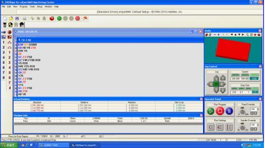
Steps for running the CNC Part Program:
- Click on the Home icon.

- Machine Home Window will load.
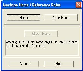
- Click on the Home button.
- The machine will now home all three axes. Wait until the homing is completed.
- Select file > open.
- Navigate to the folder containing the File.
- Select the file and click open.
- Using tool path verification, you can check for programming errors before running a part program. Select Program > verify. The verify program dialogue box appears.
- Check verify program then watch the verify window.
- When the verification is completed, the normal program stop dialogue box appears. Click OK.
- Before executing the program, make sure that all safety procedures have been taken.
- Open the door of the CNC Milling Machine by clicking on the icon for Output 8 from the Outputs toolbar.
- Open the jaws of the vise by clicking on the icon for Output 7 from the Outputs toolbar.
- Load a raw stock into the vise manually.
- Close the jaws of the vise by clicking on the icon for Output 7 from the Outputs toolbar.
- Close the door of the CNC Milling Machine by clicking on the icon for Output 8 from the Outputs toolbar.
- Select run/continue command from the program menu. The run program dialogue box appears.
- Make sure that the Start Line box is set to line 1of the program.
- Click the run settings buttons. The Run setting dialogue box appears.
- Make desired changes in the Run setting dialog box, and select OK.
- Check run button
 to begin run your program. Run program menu is displayed as follows.

- Please verify the ATC configuration message will be displayed.
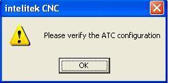
- Click on OK.
- Configure ATC window will be displayed.
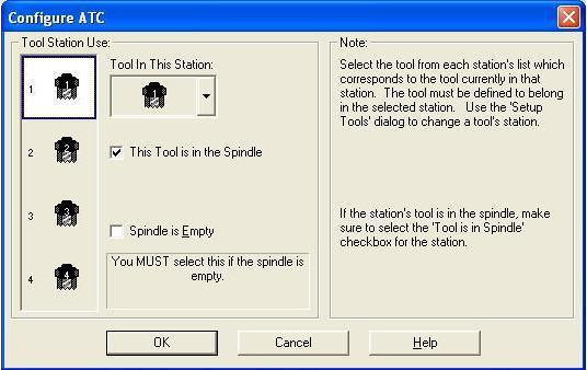
- Look at the Mill and verify that the tool shown on the window is physically present in the spindle.
- The program will run.
- After the part machining is completed, wait until all operations have stopped.
Steps for system shutdown:
- In CNCBase software, click on the red stop button and OK.
- Click on the Home icon to home all the 3 axes of the machine and wait until homing is completed.
- Open the door of the CNC Milling Machine by clicking on the icon for Output 8 from the Outputs toolbar.
- Open the jaws of the vise by clicking on the icon for Output 7 from the Outputs toolbar.
- Remove the machined part from the vise manually.
- Close the door of the CNC Milling Machine by clicking on the icon for Output 8 from the Outputs toolbar.
- Exit the CNCBase software do not save.
- Shut down the PC.
- Turn off the Mill controller.
- Turn off the Workstation 1 UPS.
- Turn off the Power supply to the Workstation.
- Close the valve for compressed air supply.
- Turn off the remote control switch for compressor.
- Turn off the Mains Power Supply to the FMS Lab.
- Downstairs, turn off the Mains power supply to the compressor.
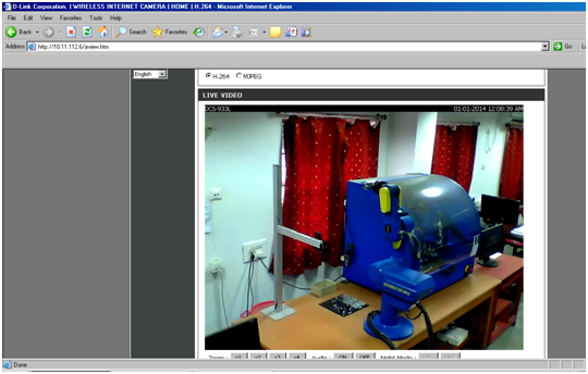
Steps for using IP camera for remotely viewing the operations of CNC:
- Open Internet Explorer browser and type http://203.110.245.36 in the address bar.
- Once the page gets loaded, the login window will come up as shown in the figure below.

Enter Username: admin
Password: 123456
- Then the IP camera page loads. If you are viewing this page for the first time, it will ask you to install the plugin as shown below.
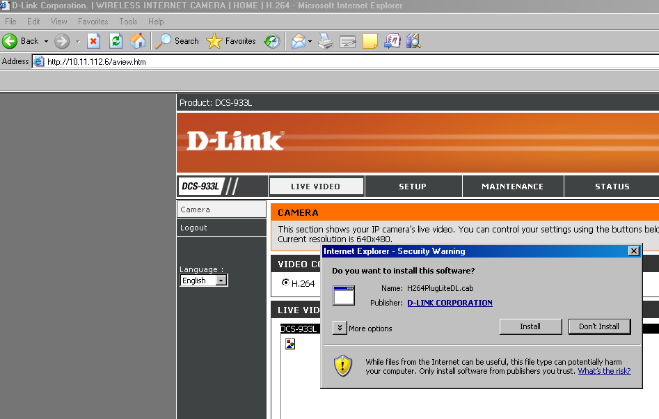
- Click on install and it will install the plugin.
- Then you will be able to view the CIM cell operations through IP camera as shown in the figure below.