Reverse Bias – Silicon Diode
INSTRUCTION
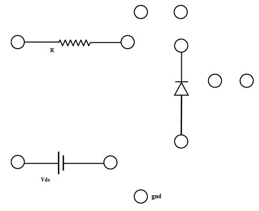
- Connect the components as mentioned below:
L1-L3, L4-L7, L8-L10, L5-L10, L6-L11,L9-L11, L9-L12.(For eg. click on 1 and then drag to 3 and so on.)
- Click on 'Check Connection' button to check the connections.
- If connected wrong, double click on the wrong connection. Else click on 'Delete all connection' button to erase all the connections.
- Set DC voltage to 0.2 V .
- Set the resistor and select diode.
- Voltmeter is placed parallel to diode and ammeter series with resistor.
- The positive of battery to the N side(cathode) and the negative of battery to the P side(anode) of a diode.
- Now vary the voltage upto 30V and note the Voltmeter and Ammeter reading for DC voltage .
- Take the readings and note Voltmeter reading across Silicon diode and Ammeter reading.
- Plot the V-I graph and observe the change.
| Serial No. |
Reverse Voltage(Volt) |
Reverse Current(μAmp) |