RC Frequency Response-LPF
INSTRUCTION
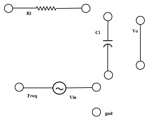
- Connect the components as mentioned below:
L1-L3, L5-L7, L4-L5, L6-L8, L6-L9, L12-L9.(For eg. click on 1 and then drag to 3 and so on.)
- Click on 'Check Connection' button to check the connections.
- If connected wrong click on 'Delete all connection' button to erase all the connections.
- Set Load Resistance(RL)=10 KΩ.
- Set Load Capacitor(CL)=0.01nF.
- The source voltage (Vin) is set to 10V.
- Keeping source voltage constant, vary the frequency from 50 Hz in regular steps.
- Click on "Add to Table" button to add the readings to the table.
- Vary the Frequency by keeping the load resistances and load capacitance constant.
- Select "Plot" button to plot the frequency graph or the phase graph of the RC frequency, Frequency(Hz) along X-axis and Magnitude(dB) along Y-axis.
- Click on "Clear" button to take another set of readings.
| Serial No. |
Frequency(Hz) |
Magnitude(dB) |
Phase(theta) |
Output Voltage(V) |