Zener Diode - LINE Regulator
INSTRUCTION
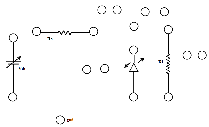
- Connect the components as mentioned below:
L1-L3, L4-L7, L8-L15, L15-L10, L11-L17, L16-L18, L17-L5, L18-L6, L13-L15, L14-L19, L9-L16, L12-L9.(For eg. click on 1 and then drag to 3 and so on.)
- Click on 'Check Connection' button to check the connections.
- If connected wrong, double click on the wrong connection. Else click on 'Delete all connection' button to erase all the connections.
- Set the Zener Voltage(VZ)= 5.1 v
- Set the Series Resistance (RS) = 1 kΩ
- Set the Load Resistance (RL) = 2 kΩ
- Vary DC voltage from 0 to 20 v.
- Voltmeter is placed parallel to load resistor and ammeter series with the series resistor.
- Choose appropriate DC voltage such that zener diode is 'on'.
- Now note the Voltmeter and Ammeter reading for various DC voltage.
- Note the Load current(IL), zener current(IZ), Output voltage(VO)
- Calculate the voltage regulation.
- Repeat the experiment for Load Resistance (RL) = 5 kΩ