
At the end of the experiment, the student would be able to
- Explain Ohm's Law
- Explain Ohm's Law for Resistance in series
- Explain Ohm's Law for Resistance in parallel
- Explain Non Ohmic Device
- Measure and confirm Ohms Law
Ohm's Law
- The law states that the current through a conductor between two points is directly proportional to the voltage across the two points. Such a conductor is characterized by its ‘Resistance’ – R measured in Ohms.
- \(V=I \times R\)
- V is the Voltage in Volts across the conductor.
- I is the current in Amperes through the conductor.
- Voltage(V) is directly proportional to current i.e \(V=I \times R\).
- Resistance(R) in inversely proportional to current(I) i.e \(I=\frac{V}{R}\)
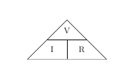
NOTE:
From the above figure, the equation may be represented by a triangle known as Ohm's Law triangle, where V (voltage) is placed on the top section, the I (current) is placed to the left section, and the R (resistance) is placed to the right. The line that divides the left and right sections indicates multiplication, and the divider between the top and bottom sections indicates division.
Therefore equations derived from Ohm's law triangle are-$$V=I \times R$$
$$I= \frac{V}{R}$$
$$R = \frac{V}{I}$$
Explaination of Ohm's Law
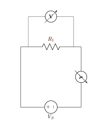
From the circuit:
The voltage across resistor is equal to source voltage:
$$V_R=V_S$$
The current through the resistance is given by:
$$I=\frac{V_R}{R}$$
Explaination of Ohm's Law for Resistance in series
Series circuits are sometimes called current-coupled or daisy chain-coupled. The current in a series circuit goes through every component in the circuit. Therefore, all of the components in a series connection carry the same current. There is only one path in a series circuit in which the current can flow.
Current:
$$I=I_1=I_2=I_3$$
Resistance:
$$R_{eq}=R_1+R_2+R_3$$
Voltage:
$$V_S=V_{R1}+V_{R2}+V_{R3}$$
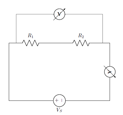
From the circuit:
The equivalent resistance,
$$R_{eq}=R_1+R_2$$
The total current of the circuit,
$$I_T=\frac{V_S}{R_{eq}}$$
Voltage across each resistance are,
For resistance \(R_1\),
$$V_{R1}=R_1 \times I_T$$
For resistance \(R_2\),
$$V_{R2}=R_2 \times I_T$$
In a series circuit, the current through each of the resistors is the same, and the voltage across the circuit is the sum of the voltages across each resistor.
Explaination of Ohm's Law for Resistance in parallel
If two or more components are connected in parallel they have the same potential difference (voltage) across their ends. The potential differences across the components are the same in magnitude, and they also have identical polarities. The same voltage is applicable to all circuit components connected in parallel. The total current is the sum of the currents through the individual components, in accordance with Kirchhoff’s current law.
Voltage:
$$V=V_1=V_2=V_3$$
Resistance:
$$\frac{1}{R_{eq}}=\frac{1}{R_1}+\frac{1}{R_2}+\frac{1}{R_3}$$
Current:
$$I_T=I_{R1}+I_{R2}+I_{R3}$$
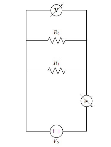
From the circuit:
The equivalent resistance,
$$ R_{eq}=\frac{R_1 \times R_2}{R_1+R_2}$$
The total current of the circuit,
$$I_T=\frac{V_S}{R_{eq}}$$
Current across each resistance are,
For resistance \(R_1\),
$$ I_{R1}=\frac{V_S}{R_1}$$
For resistance \(R_2\),
$$ I_{R2}=\frac{V_S}{R_2}$$
In a parallel circuit, the voltage across each of the resistors is the same, and the total current is the sum of the currents through each resistor.
Explaination of Non Ohmic Device
A Non ohmic device is a device that does not obey Ohm's Law i.e. the resistance is not constant, but changes in a way that depends on the voltage across it.The device is said to be non-Ohmic. In this case V versus I graph is not a straight line, but has some curvy shape. Such devices do not have a constant value of resistance and the resistance is called dynamic resistance because it is constantly changing.Examples of such devices are tungsten filament (bulb), diode,thermistor etc.
Note
- Ohms Law is a very useful law but it only applies to devices that behave like resistors – ie – I is simply proportional to V.
- Ohms Law describes one possible relationship between V and I in a component, but there are others, like
- Capacitors ( I proportional to rate of change of V )
- Diodes ( I flows in only 1 direction )
- Thermistors ( Temperature dependent resistors )

- Let us go through the experiment of confirming Ohms Law.
- Set DC voltage(0-30 V).
- Set the Resistance Value(1 Kohm - 100 Kohm) .
- Voltmeter is placed parallel to resistor and ammeter series with resistor.
- Now note the Voltmeter and Ammeter reading for DC voltage.
- Increase the DC voltage by 2 factor and note Voltmeter and Ammeter Readings. Keep resistance value constant
- Plot the V-I graph to verify Ohm's Law.
- Repeat step 2 to 6 for another set of resistance value.
- V versus I graph is a straight line.
- Therefore from the graph we see that the resistance do adhere to Ohm’s law. Thus resistance is said to be an Ohmic device.
- Let us go through the experiment of confirming Ohms Law with Resistance in series.
- Set DC voltage(0-30 V).
- Here resistance are kept in series. Set the resistance R1(1 Kohm - 100 Kohm) value and set resistance R2(5 - 15 Kohm).
- Voltmeter is placed parallel with resistor and ammeter series with resistor.
- Now note the Voltmeter and Ammeter reading for DC voltage.
- Increase the DC voltage by 2 factor and note Voltmeter and Ammeter Readings. Keeping resistance value constant
- Plot the V-I graph to verify Ohm's Law
- Repeat step 2 to 6 for another set of resistance value.
- Let us go through the experiment of confirming Ohms Law with Resistance in parallel.
- Set DC voltage(0-30 V).
- Here Resistances are kept parallelly. Set the resistance R1 (100 ohm- 2 kohm) value and set resistance R2(1 -30 kohm).
- Voltmeter is placed parallel to resistor and ammeter series with resistor.
- Now note the Voltmeter and Ammeter reading for DC voltage.
- Increase the DC voltage by 2 factor and note Voltmeter and Ammeter Readings. Keeping Resistance value constant
- Plot the V-I graph to verify Ohm's Law.
- Repeat step 2 to 6 for another set of resistance value.
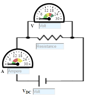
Figure:1
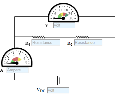
Figure:2
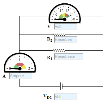
Figure:3
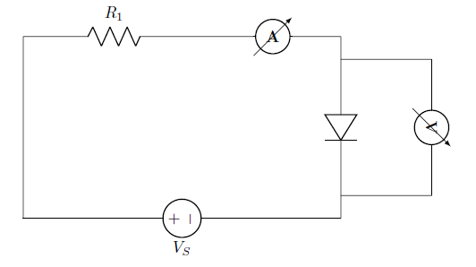
- Let us go through the experiment of confirming Non Ohmic Device.
- Set DC voltage to 5 V .
- Use the resistor of 100K ohms and a diode.
- Voltmeter is placed parallel to Silicon diode and ammeter series with resistor.
- Now note the Voltmeter and Ammeter reading for DC voltage 5V.
- Decrease the Resistance as 75K, 51K, 24K and 10K Ohms and take the readings and note Voltmeter reading across Silicon diode and Ammeter reading.
- Plot the V-I graph and observe the change.
- The Change is not simply proportional. V versus I graph is not a straight line.
- Therefore from the graph we see that the diode does not adhere to Ohms law.Thus diode is said to be non-Ohmic device.
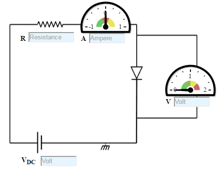
Figure:4


Test Your Knowledge!!

- A 3 volt battery sends a current of 1 ampere through a light bulb. What is the
resistance of the filament of the bulb?
[Ans:3Ω]
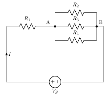
- Determine the value of \(R_5\) and current through it (\(I_{R5}\)), if current through
branch AB is zero and \(R_1\)=1Ω,\(R_2\)=1.5 Ω,\(R_3\)=2Ω,\(R_4\)=4 Ω,\(V_S\)=10 V.
[Ans:\(R_5\)=6Ω and \(I_{R5}\)=0.5 A]
- A 50Ω resistor is in parallel with 100Ω resistor. Current in 50Ω
resistor is 7.2 A. How will you add a third resistor and what will be its value of the line-current is to
be its value if the line-current is to be 12.1 amp ?
[Ans:Third resistance must be connected in parallel with 277Ω]
- A resistor of 12 Ω is connected in series with a combination of 15 Ω and 20 Ω resistor in parallel.
When a voltage of 120 V is applied across the whole circuit find the current taken from the supply.
[Ans:5 A ]
- Three parallel connected resistors when connected across a d.c. voltage source dissipate a total
power of 72 W. The total current drawn is 6 A, the current flowing through the first resistor is
3 A and the second and third resistors have equal value. What are the resistances of the three
resistors ?
[Ans:4Ω, 8Ω, 8Ω ]
- Calculate the voltage drop across the following electrical loads:
- The bulb that has 2.4 amperes flowing through it. The resistance of the
bulb is 16 ohms.
[Ans:38.4V]
- A coffee grinder that has a resistance of 85 ohms and a current of 1.41
amperes flowing through it.
[Ans:119.85V]
- A current of 0.024 amperes flowing through a resistance of 750 ohms.
[Ans:18V]
- The bulb that has 2.4 amperes flowing through it. The resistance of the
bulb is 16 ohms.
- A resistance of 10 Ω(\(R_1\)) is connected in series with two resistances each of 15 Ω(\(R_2\) and \(R_3\))
arranged in parallel. What resistance(\(R_4\)) must be shunted across
this parallel combination so that the total current taken shall
be 1.5 A with 20 V applied ?
[Ans:\(R_4\)=6Ω]
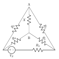
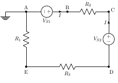
- Compute the relative potentials of points A, B, C, D and E which
point A is grounded. Calculate the voltage drop across resistance \(R_1\)? Does it affect the circuit operation or potential
difference between any pair of points ?[where, \(R_1\)=6Ω,\(R_2\)=2 Ω,\(R_3\)=4Ω,\(V_{S1}\)=34 V,\(V_{S2}\)=10 V,I=2 A].
[Ans:V=12 V]

Book:
- B.L. Theraja, A.K. Theraja-A Textbook of Electrical Technology,Volume 1 Basic Electrical Engineering, S. Chand & Company LTD.,Ram Nagar, New Delhi-110 055