
Objective: Three phase power measurement by two wattmeter method.
[Fig 1: Connection diagram for three phase power measurement using two wattmeter method]
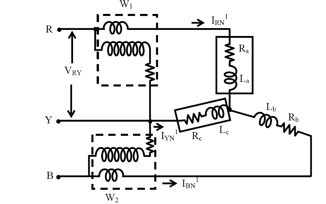
The connection diagram for the measurement of power in three phase power measurement circuit using two wattmeter's method is shown in figure 1. This is irrespective of the circuit connection star or delta. The circuit may be taken as balanced or unbalanced one, balanced type being only a special case. Please note the connection of two wattmeter's. The current coil of the wattmeter's 1 and 2 in series with R and B phase with the pressure voltage coils being connected across R-Y and B-Y respectively. Y is the third phase in which no current coil is connected.
If star connected circuit is taken as an example the total instantaneous power consumed in the circuit is,
`W= I_(RN)*V_(RN) + I_(YN)*V_(YN) + I_(BN)*V_(BN)` . . . (1)
Each of the terms in the above expression equation (1) is the instantaneous power consumed by the phases. From the connection diagram, the circuit in and the voltages across the respective (current, pressure or voltage) coils in the wattmeter, W1 are `I_(RN)` and ` V_(RY) = V_(RN) - V_(YN)`.
So, the instantaneous power measured by the wattmeter W1 is
`W_1 = I_(RN)*V_(RY)`.
Similarly the instantaneous power measured by the wattmeter W2 is . `W_2 = I_(BN)*V_(BY) = I_(BN)* (V_(BN) - V_(YN))`
Some of the two readings as given above is,

Equation (1) is compared with equation (3) to give the total instantaneous power consumed in the circuit . They are found to be same. The phasor diagram of three phase balanced star connected circuit is shown in figure 2.
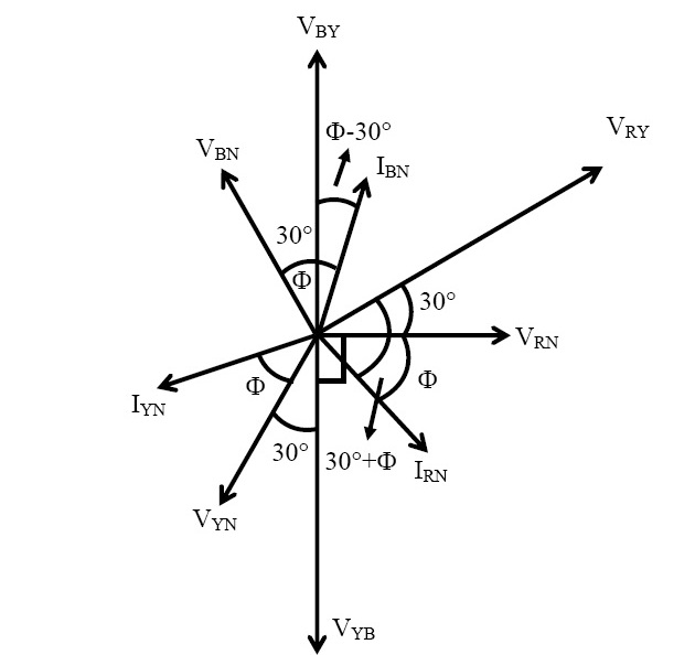
[Fig 2: Phasor diagram of three phase balanced star connected circuit]

BALANCED LOAD :
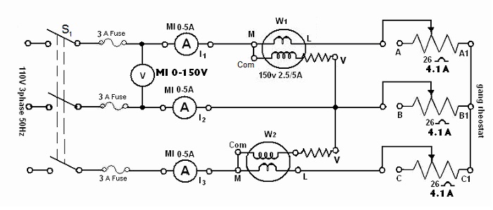
Fig. 1. Three phase power measurement circuit under balance condition
- Connect the circuit as shown in Fig. 1.
- Adjust the ganged rheostat for the maximum resistance.
- Switch on the supply.
- Close switch `S_1`.
- Read the meters to obtain `V_L, I_1, I_2` and `I_3`. Note the wattmeter reading `W_1` and `W_2`(Note the multiplying factor on the wattmeter).
- Vary the load resistance and obtain at least five sets of observations, the current should not exceed the limit (4.1 A).
- Connect the circuit as shown in Fig. 2.
- Replace the ganged rheostat by three separate rheostats of 26 Ω, 4.1 A and connect in a star.
- Adjust the three rheostats at the maximum values.
- Switch on the supply and set the autotransformer to 110 V.
- Close switch S1 and take five sets of observation for different rheostat settings such that the reading of `I_1`, `I_2`and `I_3` in each set is appreciably different to create unbalanced loading condition. The current should not exceed the limits in each arm.
UNBALANCED LOAD :
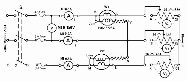
Fig. 2. Three phase power measurement circuit under unbalance condition

Minimum System Requirement:
- A standard PC running Microsoft Windows XP, Windows Vista.
- 512MB RAM and 500 MB of available hard-disk space is recommended
- 1024x768 or higher screen resolution;
- a mouse or other pointing device
- A CD-ROM drive

The simulator for this experiment is designed based on JavaScript platform combined with HTML5 Canvas for graphics. So the users are recommended to use browsers with HTML5 compatible.
Link to the simulator:
Click here to perform the Experiment

Test Your Knowledge!!

A) Book Name:
1) A. Chakrabarti, Circuit Theory (Analysis and Synthesis). Fifth Edition : 2006, Dhanpat Rai and Co.
2) A. Bruce Carlson, Circuits. First Reprint :2002, Thomson Asia Pte Ltd.
3) Parker Smith, Problems in Electrical Engineering. Ninth Edition :2003 , M/s Constable and Company, London.
B) Video Lecture:
Click here for NPTEL Video Lecture