
Objective: Verification of Maximum Power Transfer Theorem.
Maximum power is transferred from a source of given voltage and an internal impedance to the load impedance ZL in the following circuit shown in figure 1, under three conditions.
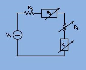
[Fig 1: Circuit diagram with source and load impedance(i.e. ZS and ZL )]
1. When only XL is adjustable:
Under this condition the power consumed by the load (I2*RL) is maximum, when I is maximum, since RL is constant.
`I= V_s/(R_s + jX_s + R_L + jX_L) . . . (1) `
`|I|_max = V_s/(R_s+R_L) . . . . . . . . . . . (2) `
when `X_L = -X_s`
This means that if the load reactance(XL) is made equal magnitude and opposite in sign to the internal reactance(Xs), the power transferred is maximum.
2. When only RL is adjustable:
From equation (1) in section (1), one may write,
`P = |I^2|*R_L = (V_s^2*R_L)/((R_s+ R_L)^2 +(X_s+ X_L)^2) . . . (3) `
Differentiating the equation (3) w.r.t RL and equating to zero, one obtains.
`R_L = sqrt(R_s^2+ (X_s+X_L)^2) . . . . . . . . . . . . . . . . . . . (4)`
3. When both RL and XL are adjustable:
Under this condition both equation (2) and (4) are valid simultaneously and one obtains.
`R_L = R_s , X_L = -X_s`

Circuit Diagram
.jpg)
[Fig 1: Circuit diagram of experimental set-up for verification of maximum power transfer theorem]
1. When only XL is adjustable:
- Take a suitable set of values of Vs, XS, XL as shown in the figure. You can choose XS to be inductive (Ls) and capacitive (Cs). XL can choose as inductive(LL) and capacitive (CL) to the load.
- Next choose a suitable load resistance (RL).
- For the maximum power theorem, the condition would be RL=RS, XS(i.e. X1)=-XL.(i.e. X2)
Where,


Take an example, put Ls=1mH, Cs=10.1µF.
Now for different value of Cs, note down V1 and V4.
Load power (PL) = I2*RL = I*I*RL = (V1/100)*V4
= K*V1*V4
where K=1/100 = 1/Rs
Enter the value of the voltage for different values of Cs and obtain the set corresponding to the maximum value of (V1*V4). Verify that for this set V2=V6.
2. When only RL is adjustable:
Repeat the procedure of part (1), with Cs fixed and RL varied. At the point of maximum power check `R_L = sqrt(R_s^2 + (X_1 + X_2)^2)` and VRL=V4.
3. When both RL and XL are adjustable:
Repeat the procedure of part (2), varying Cs and obtain the maximum power condition.
Check under this condition,
VRL= VRS i.e. V1=V4 ;
VLS= VCL i.e. V2=V6 ;

Minimum System Requirement:
- A standard PC running Microsoft Windows XP, Windows Vista.
- 512MB RAM and 500 MB of available hard-disk space is recommended
- 1024x768 or higher screen resolution;
- a mouse or other pointing device
- A CD-ROM drive

The simulator for this experiment is designed based on JavaScript platform combined with HTML5 Canvas for graphics. So the users are recommended to use browsers with HTML5 compatible.
Link to the simulator:
Click here to perform the Experiment

Test Your Knowledge!!

A) Book Name:
1) A. Chakrabarti, Circuit Theory (Analysis and Synthesis). Fifth Edition : 2006, Dhanpat Rai and Co.
2) A. Bruce Carlson, Circuits. First Reprint :2002, Thomson Asia Pte Ltd.
3) Parker Smith, Problems in Electrical Engineering. Ninth Edition :2003 , M/s Constable and Company, London.
B) Video Lecture:
Click here for NPTEL Video Lecture