
Objective: To Verify Tellegen's Theorem.
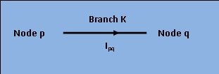
[Fig 1: Current $I_{pq}$ flowing through branch K between node 'p' and 'q'.]
For any given time, the sum of power delivered to each branch of any electric network is zero.
Thus for \(K^{th}\) branch, this theorem states that, \[ \sum_{k=1}^n V_k i_k = 0 \] n being the number of branches, \(V_K\) the drop in the branch and \(i_K\) the through current. while \(V_p\) and \(V_q\) are voltages at p and q nodes. We have,
\[ V_Ki_{pq} = (V_p-V_q)i_{pq} = V_Ki_k .....(1)\] \[ Also, V_Ki_{pq} = (V_q-V_p)i_{qp} .........(2)\] \[ Obviously, i_{pq} = -i_{qp} ...............(3)\] Summing equations (1) and (2),
\[ 2V_Ki_{k} = (V_p-V_q)i_{pq} + (V_q-V_p)i_{qp} \] \[ V_Ki_{k} = \frac{(V_p-V_q)i_{pq} + (V_q-V_p)i_{qp}}{2} .......(4)\] Equation (4) can be written for every branch of the network. Assuming n branches, generalisation yields,
\[ \sum_{k=1}^n V_k i_k = \frac{1}{2} \sum_{p=1}^n \sum_{q=1}^n (V_p-V_q)i_{pq} \\ = \frac{1}{2} \sum_{p=1}^n V_p \sum_{q=1}^n i_pq - \frac{1}{2} \sum_{q=1}^n V_p \sum_{p=1}^n i_pq ........(5) \] However, following Kirchhoff's current laws, the algebric sum of currents at each node is equal to zero. \[ \sum_{p=1}^n i_{pq} = 0 .......(6) \] \[ \sum_{q=1}^n i_{pq} = 0 .......(7) \] Substituting equ. (6) and (7) in equ. (5), we obtain \[ \sum_{k=1}^n V_k i_k = 0 ........(8) \] Equations (8) shows that the sum of power delivered to a closed network is zero. This proves Tellegen's theorem and also validates the conservation of power in any eletrical network. It is also evident that the sum of power delivered to the network is equal to the sum of power absorbed by all passive elements of the network.

Circuit Diagram:
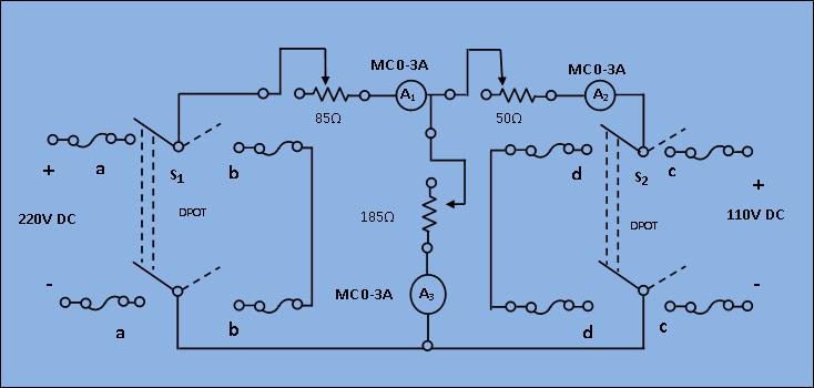
[Fig 1: Circuit diagram of experimental set-up for verification of Tellegen's theorem]
- Connect the circuit as shown in the circuit diagram above, keeping the switches open and resistance at their maximum positions.
- Case 1: In presence of both the sources
Select switch of S1 to Power and S2 to Power and switch on the supply to get the ammeter readings. Observe the power supplied in +ve and power dissipated in -ve by the elements and voltage source for this condition. - Case-2: In presence of V1 only
Select switch of S1 to Power and S2 to short and switch on the supply. Read the corresponding power values as done in the above case.
- Case-3: In presence of V2 only
Select switch of S1 to Short and S2 to switch on the supply. Read the corresponding power values.
Calculate the power consumed or delivered by each element for each case and check if power absorbed = power delivered. This proves the Tellegen's theorem.

Minimum System Requirement:
- A standard PC running Microsoft Windows XP, Windows Vista.
- 500MB RAM and 500 MB of available hard-disk space is recommended
- 1024x768 or higher screen resolution;
- a mouse or other pointing device
- A CD-ROM drive

The simulator for this experiment is designed based on JavaScript platform combined with HTML5 Canvas for graphics. So the users are recommended to use browsers with HTML5 compatible.
Link to the simulator:
Click here to perform the Experiment

Test Your Knowledge!!

A) Book Name:
1) A. Chakrabarti, Circuit Theory (Analysis and Synthesis). Fifth Edition : 2006, Dhanpat Rai and Co.
2) A. Bruce Carlson, Circuits. First Reprint :2002, Thomson Asia Pte Ltd.
3) Parker Smith, Problems in Electrical Engineering. Ninth Edition :2003 , M/s Constable and Company, London.
B) Video Lecture:
Click here for NPTEL Video Lecture