
Objective:
To determine the self-inductance of an unknown coil.
This bridge circuit measures an inductance by comparison with variable standard self inductance. The connections for balance condition is shown in Fig. 1.
Circuit Diagram:
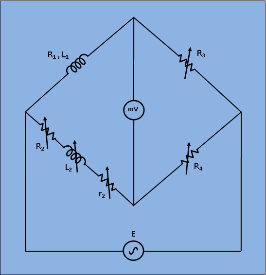
[Fig 1: Circuit Diagram for Measurement of Self Inductance by Maxwell Bridge]
Let,
`L_1`= Unknown self Inductance of resistance `R_1`,
`L_2`= variable inductance of fixed resistance `r_2`,
`R_2`= variable resistance connected in series with inductor `L_2`,
`R_3`,`R_4`= known non inductive resistances,
At balance condition,
`(R_1 +jomegaL_1)*R_4 = (R_2 + r_2 + jomegaL_2)*R_3` ...(1)
Equating both the real and imaginary parts in eq.`(1)` and seperating them,
`L_1 =(R_3/R_4)L_2` ...(2)
`R_1 = (R_3/R_4)*(R_2+r_2)` ...(3)
Resistors `R_3` and `R_4` are normally a selection of values from 10, 100, 1000 and 10,000 `Ω`. `r_2` is a decade resistance box.


[Fig. 1. Circuit digram of experimental set-up for Maxwell Bridge]
1) Apply Supply voltage from the signal generator with arbitrary frequency. ( V =3v). Also set the unknown Inductance value from 'Set Inductor Value' tab.
2) Then switch on the supply to get millivoltmeter deflection.
3) Choose the values of L2, r2, R2, R3 and R4 from the inductance and resistance box. Varry the values to some particular values to achieve "NULL".
4) Observe the millivoltmeter pointer to achieve "NULL".
5) If "NULL" is achieved, switch to 'Measure Inductor Value' tab and click on 'Simulate'. Observe the calculated values of unknown inductance (L1) and it's internal resistance (R1) of the inductor.
6) Also observe the Dissipation factor of the unknwown inductor which is defined as `(omegaL)/R`. Where, `omega=2pif`.

Minimum System Requirement:
- A standard PC running Microsoft Windows XP, Windows Vista.
- 512MB RAM and 500 MB of available hard-disk space is recommended
- 1024x768 or higher screen resolution;
- a mouse or other pointing device
- A CD-ROM drive

The simulator for this experiment is designed based on JavaScript platform combined with HTML5 Canvas for graphics. So the users are recommended to use browsers with HTML5 compatible.
Link to the simulator:
Click here to perform the Experiment

Test Your Knowledge!!

A) Book Name:
Book Name:
1) A.K. Sawhney, Electrical and Electronic Measurements and Instrumentation, Reprinit 2010 : Dhanpat Rai & Co.
2) A. Bruce Carlson, Circuits. First Reprint :2002, Thomson Asia Pte Ltd.
B) Video Lecture:Click here for NPTEL Video Lecture