
Objective: To Verify Norton Theorem.
A linear active network consisting of independent and(or) dependent voltage and current sources and linear bilateral network elements can be replaced by an equivalent circuit consisting of current sources in parallel with the resistance, the current source being the short circuited current across the load terminal and resistance being the internal resistance of the source network looking through the open circuited load terminals. In order to find the current through \(R_L\), the load resistance of the figure 1 by Norton's theorem, let, replace \(R_L\) by short circuit as shown in figure 2.

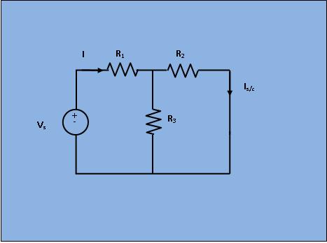
Obviously, in Fig 2;
\begin{align}
I & = \frac{V_s}{R_1+\frac{R_2 * R_3}{R_2 + R_3}} \\ \\
I_{s/c} & = I * \frac{R_3}{R_3 + R_2}
\end{align}
Next, the short circuit is removed and the independent source is deactivated as shown in figure 3.
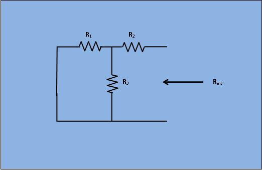
From Fig 3;
\begin{align}
R_{int} & = R_2+ \frac{R_1*R_3}{R_1+R_3}
\end{align}
As per Norton's theorem , the equivalent circuit as shown in figure 4, would contain a current source in parallel to the internal resistance, the current source
being the short circuited current across the shorted terminals of the load resistor.
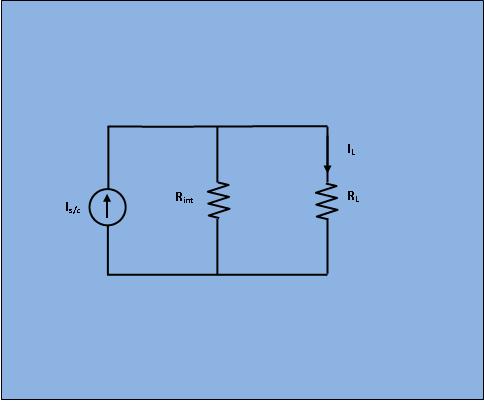
Obviously, from Fig 4; \begin{align} I_{L} & = I_{s/c}* \frac{R_{int}}{R_{int}+R_L} \end{align}


- Keep all the resistance close to their maximum respective values.
- Close the switch \(s_1\) to "aa" and \(s_2\) to "cc" positions. Observes the load current (\(I_L\)) and voltage (\(V_L\)) readings. The load resistance,
\begin{align}
R_{L} & = \frac{V_{L}}{I_{L}}
\end{align}
- Short the load terminals and find the short circuited current(\(I_{sc}\)).
- Next, compute the resistance (\(R_{int}\)) of the network as seen from the load terminals,
- Replace the 220 V source by a short by closing \(s_1\) to "bb".
- Apply V=110 V at the output terminals by closing \(s_2\) to "dd". Read the current from ammeter (I) and get \begin{align} R_{int} & = \frac{V}{I} \end{align}
- Now compute the load current (\(I_L\)) applying Norton theorem. \begin{align} I_L & = I_{sc}*\frac{R_{int}}{(R_{int}+R_L)} \end{align}
- Compare the above computed load current with its observed value in step (2) and verify the theorem.

Minimum System Requirement:
- A standard PC running Microsoft Windows XP, Windows Vista.
- 512MB RAM and 500 MB of available hard-disk space is recommended
- 1024x768 or higher screen resolution;
- a mouse or other pointing device
- A CD-ROM drive

The simulator for this experiment is designed based on JavaScript platform combined with HTML5 Canvas for graphics. So the users are recommended to use browsers with HTML5 compatible.
Link to the simulator:
Click here to perform the Experiment

Test Your Knowledge!!

A) Book Name:
1) A. Chakrabarti, Circuit Theory (Analysis and Synthesis). Fifth Edition : 2006, Dhanpat Rai and Co.
2) A. Bruce Carlson, Circuits. First Reprint :2002, Thomson Asia Pte Ltd.
3) Parker Smith, Problems in Electrical Engineering. Ninth Edition :2003 , M/s Constable and Company, London.
B) Video Lecture:
Click here for NPTEL Video Lecture