
To Verify Millman's Theorem.
This theorem is a combination of Thevenin's and Norton's theorems.
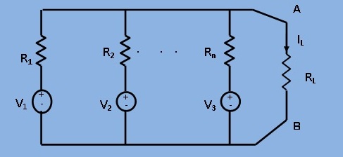
When a number of voltage sources (V1,V2,...,Vn) are in parallel having internal resistances (R1,R2,...,Rn) respectively,
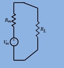
the arrangement can be replaced by a single equivalent voltage source Vm
in series with an equivalent series resistance Rm as given below in Fig.1 and Fig.2.
As per Millman's Theorem ,
$$V_m = \frac{(+- V_1G_1 +- V_2G_2 +-.........+- V_nG_n)}{(G_1+G_2+.........+G_n)}$$ where,$$G_i = \frac{1}{R_i}$$ $$i = 1,2,....,n$$ $$R_m = \frac{1}{G} = \frac{1}{(G_1+G_2+.........+G_n)}$$
This voltage represents the Millman's equivalent voltage
Vm.
The resistance Rm can be found , as usual , by replacing each voltage source by a short circuit.
If there is a load resistance RL across the terminals A and B ,
then the load current IL is given by

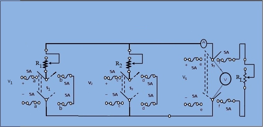
Fig.1 The circuit diagram of Millman's theorem
1. Keep all the resistance values between 1 - 10 kΩ.
2. Close the switch S1 to "aa" and S2 to "cc" positions and S3 to "ff" positions. Observe the load current (IL).
3. Remove the load by opening the switch S3 and read the open circuit voltage (or Millman's equivalent voltage) Vm.
4. Next, compute the equivalent resistance (Rm) of the network as seen from the load terminals.
a. Replace the 220 V source by a short by closing S1 to "bb" and S2 to "dd".
b. Apply 110 V at the output terminals by closing S3 to "ee". Read the voltmeter (V) and ammeter (I) and get
$$ R_m = \frac{V}{I} $$ 5. Now compute the load current. Applying Millman's theorem.
$$ I_L = \frac{V_m}{(R_m+R_L)} $$

Minimum System Requirement:
- A standard PC running Microsoft Windows XP, Windows Vista.
- 512MB RAM and 500 MB of available hard-disk space is recommended
- 1024x768 or higher screen resolution;
- a mouse or other pointing device
- A CD-ROM drive

The simulator for this experiment is designed based on JavaScript platform combined with HTML5 Canvas for graphics. So the users are recommended to use browsers with HTML5 compatible.
Link to the simulator:
Click here to perform the Experiment

Test Your Knowledge!!

A) Book Name:
Book Name:
1) A. Chakrabarti, Circuit Theory (Analysis and Synthesis). Fifth Edition : 2006, Dhanpat Rai and Co.
2) A. Bruce Carlson, Circuits. First Reprint :2002, Thomson Asia Pte Ltd.
3) Parker Smith, Problems in Electrical Engineering. Ninth Edition :2003 , M/s Constable and Company, London.
B) Video Lecture:
Click here for NPTEL Video Lecture